Hacking Hardware Picofly - a HWFLY switch modchip

Darkspade

Active Member
Newcomer
Joined
Jul 29, 2022
Messages
32
Trophies
0
Age
46
Location
80817
XP
367
Country
United States
i have the same problem, is safe this for ban?
I used Sysnand w/ CFW (your S/N is blocked) , only used nro daybreak to update.. don't install anything from sysnand w/cfw (nsp,xci,nsz)..
I used HATs pack for this.. Safe? (there is always risks when using a modded Console).. not sure if you an update in recovery mode easier.. I just did it this way
 

Donnie-Burger

Well-Known Member
Member
Joined
Oct 27, 2021
Messages
927
Trophies
0
Website
www.youtube.com
XP
1,804
Country
United States
I used Sysnand w/ CFW (your S/N is blocked) , only used nro daybreak to update.. don't install anything from sysnand w/cfw (nsp,xci,nsz)..
I used HATs pack for this.. Safe? (there is always risks when using a modded Console).. not sure if you an update in recovery mode easier.. I just did it this way
I use OFW thats clean to update since thats the point of dual boot for me, keep OFW safe. Can do anything an off the shelf switch can do. I also updated emummc with daybreak on one console and all good. Have not had a single issue with, sleep or ofw so I removed all usbc ports, buttons and 3v regulator on the zeros. Side note - They all glitch faster than hwfly's on average. Amazing work has been done here. Next is to try with mosfets since low on flex cables.
 

Darkspade

Active Member
Newcomer
Joined
Jul 29, 2022
Messages
32
Trophies
0
Age
46
Location
80817
XP
367
Country
United States
I use OFW thats clean to update since thats the point of dual boot for me, keep OFW safe. Can do anything an off the shelf switch can do. I also updated emummc with daybreak on one console and all good. Have not had a single issue with, sleep or ofw so I removed all usbc ports, buttons and 3v regulator on the zeros. Side note - They all glitch faster than hwfly's on average. Amazing work has been done here. Next is to try with mosfets since low on flex cables.

OFW was broken for me i couldn't boot into it without the help of atmos..
 

lightninjay

Well-Known Member
Member
Joined
Mar 28, 2023
Messages
560
Trophies
0
Age
31
XP
1,382
Country
United States
As mentioned earlier, I just did an install on a patched V1 Pokemon Let's Go edition console. The chip appears to show all the proper LED's (Blue, then white for eMMC write,then green for success. Subsequent boots just go from blue to green) but the console just boots like normal. Admittedly, I did rip the traces of the left capacitor when soldering the CPU mosfet, but managed to solder the mosfet to the right-side capacitor instead.

Any advice, or should I just try to recover and leave this switch unhacked? Thanks
 

Darkspade

Active Member
Newcomer
Joined
Jul 29, 2022
Messages
32
Trophies
0
Age
46
Location
80817
XP
367
Country
United States
As mentioned earlier, I just did an install on a patched V1 Pokemon Let's Go edition console. The chip appears to show all the proper LED's (Blue, then white for eMMC write,then green for success. Subsequent boots just go from blue to green) but the console just boots like normal. Admittedly, I did rip the traces of the left capacitor when soldering the CPU mosfet, but managed to solder the mosfet to the right-side capacitor instead.

Any advice, or should I just try to recover and leave this switch unhacked? Thanks

did you need to solder the RGB piont on the Chip?
 
  • Like
Reactions: Ricky_25

impeeza

¡Kabito!
Member
Joined
Apr 5, 2011
Messages
6,412
Trophies
3
Age
46
Location
At my chair.
XP
19,003
Country
Colombia
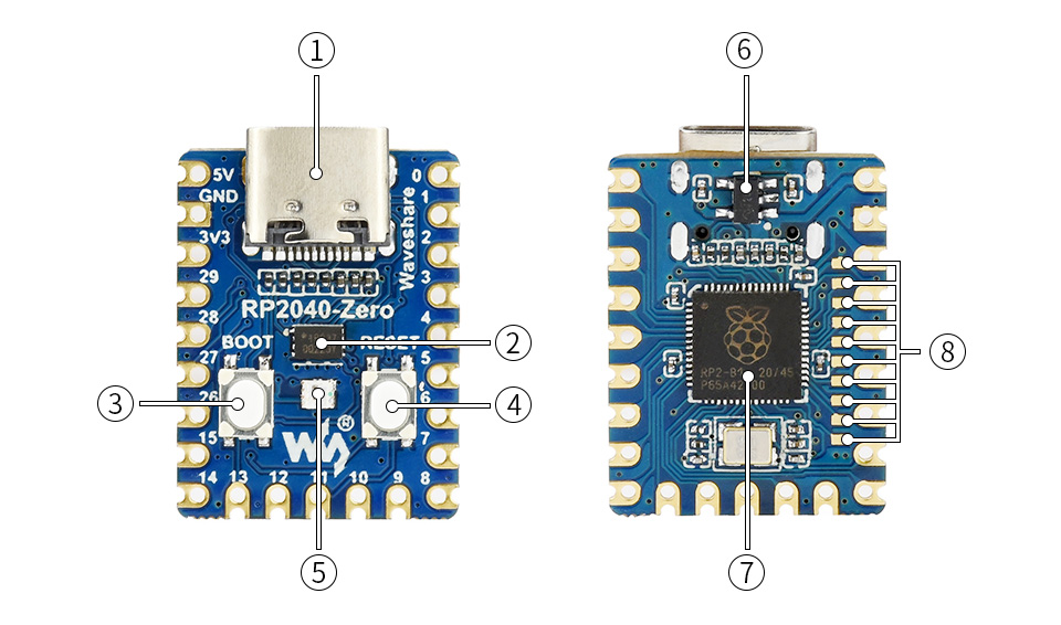
Can you circle which part is the 3v regulator and is it important? Im sure to remove usbc and buttons but i dont know about 3v regulator
The 3V3 regulator allows you to use the chip from USB voltage, converts 5V from USB or the 22 pin to 3V3 required by the chip, once you remove it you CAN NOT connect again to USB because there is no level shift.

RP2040-Zero-details-intro.jpg


  1. USB Type-C connector
  2. W25Q16JVUXIQ
    2MB NOR-Flash
  3. BOOT button
    press it when resetting to enter download mode
  4. RESET button
  5. WS2812
    cool RGB LED
  6. ME621 THIS IS THE 3V3 LEVEL SHIFTER.
    low dropout LDO, max current 800MA
  7. RP2040
    dual-core processor, up to 133MHz operating frequency
  8. RP2040 pins
    10x solder points, 9 of which are for GPIO
Source:
https://www.waveshare.com/rp2040-zero.htm
 

Dandan0404

Well-Known Member
Member
Joined
Mar 25, 2023
Messages
131
Trophies
0
Age
23
XP
183
Country
Philippines
The 3V3 regulator allows you to use the chip from USB voltage, converts 5V from USB or the 22 pint to 3V3 required by the chip, once you remove it you CAN NOT connect again to USB because there is no level shift.

RP2040-Zero-details-intro.jpg


  1. USB Type-C connector
  2. W25Q16JVUXIQ
    2MB NOR-Flash
  3. BOOT button
    press it when resetting to enter download mode
  4. RESET button
  5. WS2812
    cool RGB LED
  6. ME621 THIS IS THE 3V3 LEVEL SHIFTER.
    low dropout LDO, max current 800MA
  7. RP2040
    dual-core processor, up to 133MHz operating frequency
  8. RP2040 pins
    10x solder points, 9 of which are for GPIO
Source:
https://www.waveshare.com/rp2040-zero.htm
Last question, i have an OLED, after removing usb c and buttons ( probably regulator) does it fit on the back without cutting bulging anything? Anyone know the best spot/placement?
 
  • Like
Reactions: Donnie-Burger

Donnie-Burger

Well-Known Member
Member
Joined
Oct 27, 2021
Messages
927
Trophies
0
Website
www.youtube.com
XP
1,804
Country
United States
Last question, i have an OLED, after removing usb c and buttons ( probably regulator) does it fit on the back without cutting bulging anything? Anyone know the best spot/placement?
20230330_210401.jpg

Kapton tape over chip once all tests are good to avoid any shorts. Cut kapton tap a little smaller to not cover wifi connection. No bulge. I re-routed reset wire around coil to not cover bq and get smashed by thermal pad.
 
Last edited by Donnie-Burger,

lightninjay

Well-Known Member
Member
Joined
Mar 28, 2023
Messages
560
Trophies
0
Age
31
XP
1,382
Country
United States
Just an update, I went ahead and put in my 2nd rp2040 board after programming it and confirming the LED was the proper color after USB flash.

After installing it, the LED was showing CYAN rather than GREEN. I asked my GF to look at the first one and she confirmed it looked green, but this new one was definitely cyan. After seeing that, I went back over all my soldering joints concerning the MOSFET and CPU pins.

I am now currently able to boot to Hekate and am performing an eMMC nand backup. Strangely, it seems to have a 50/50 shot at whether Hekate IPL is loaded or not, but I have not shortened the wires and permanently installed it yet.

At any rate, I can't be upset about having to reboot one time to get into Hekate from OFW.

LET'S GO, PICOFLY FOR THE WIN!
 

dkabot

Better With Others' Systems Than Their Own
Member
Joined
Sep 9, 2014
Messages
1,042
Trophies
0
XP
626
Country
United States
After some successful boots, subsequent failure (as a consequence of the horrible hack to the chip), switching to a -ZERO like we should've started with, a further amount of successful boots, and now further subsequent failure... Any ideas?
It blinks orange (D0) currently, and boots without the chip.
 

Attachments

  • 20230402_223002.jpg
    20230402_223002.jpg
    699.6 KB · Views: 44
Last edited by dkabot,

Dee87

Well-Known Member
Member
Joined
Mar 19, 2023
Messages
1,139
Trophies
1
XP
1,578
Country
Germany
Just an update, I went ahead and put in my 2nd rp2040 board after programming it and confirming the LED was the proper color after USB flash.

After installing it, the LED was showing CYAN rather than GREEN. I asked my GF to look at the first one and she confirmed it looked green, but this new one was definitely cyan. After seeing that, I went back over all my soldering joints concerning the MOSFET and CPU pins.

I am now currently able to boot to Hekate and am performing an eMMC nand backup. Strangely, it seems to have a 50/50 shot at whether Hekate IPL is loaded or not, but I have not shortened the wires and permanently installed it yet.

At any rate, I can't be upset about having to reboot one time to get into Hekate from OFW.

LET'S GO, PICOFLY FOR THE WIN!
On the board with the 50/50 rate u need to install a second mosfet , check the aio picofly. Thread last pages there's a picture where u need to install it on Marino board
 
Last edited by Dee87,

lightninjay

Well-Known Member
Member
Joined
Mar 28, 2023
Messages
560
Trophies
0
Age
31
XP
1,382
Country
United States
On the board with the 50/50 rate u need to install a second mosfet , check the aio picofly. Three last pages there's a picture where u need to install it on Marino board
Appreciate the comment, but this is also what I feared... I think you may have missed my earlier post about how I accidentally ripped the pads of the second mosfet position, so I am basically doomed to a single mosfet setup.
 

Dee87

Well-Known Member
Member
Joined
Mar 19, 2023
Messages
1,139
Trophies
1
XP
1,578
Country
Germany
Appreciate the comment, but this is also what I feared... I think you may have missed my earlier post about how I accidentally ripped the pads of the second mosfet position, so I am basically doomed to a single mosfet setup.
what u mean u ripped of a solder pad on the Apu Xd lets see a picture
Post automatically merged:

Just an update, I went ahead and put in my 2nd rp2040 board after programming it and confirming the LED was the proper color after USB flash.

After installing it, the LED was showing CYAN rather than GREEN. I asked my GF to look at the first one and she confirmed it looked green, but this new one was definitely cyan. After seeing that, I went back over all my soldering joints concerning the MOSFET and CPU pins.

I am now currently able to boot to Hekate and am performing an eMMC nand backup. Strangely, it seems to have a 50/50 shot at whether Hekate IPL is loaded or not, but I have not shortened the wires and permanently installed it yet.

At any rate, I can't be upset about having to reboot one time to get into Hekate from OFW.

LET'S GO, PICOFLY FOR THE WIN!
the one that boots sometimes with cyan if u put a second mosfet there it will always boot to hekate.

lets see a picture of the first one with ripped of pads.please
 
Last edited by Dee87,

juanvlc

Well-Known Member
Newcomer
Joined
Jan 7, 2022
Messages
96
Trophies
0
XP
906
Country
Spain
View attachment 362824
Kapton tape over chip once all tests are good to avoid any shorts. Cut kapton tap a little smaller to not cover wifi connection. No bulge. I re-routed reset wire around coil to not cover bq and get smashed by thermal pad.
Sorry mate, with this configuration, are you able to close everything well w/o trim the back metal shield?
Regards
 
  • Like
Reactions: Donnie-Burger

Donnie-Burger

Well-Known Member
Member
Joined
Oct 27, 2021
Messages
927
Trophies
0
Website
www.youtube.com
XP
1,804
Country
United States
Sorry mate, with this configuration, are you able to close everything well w/o trim the back metal shield?
Regards
Yeah with kapton tape covering chip so nothing shorts and tape also holds it in place. Wifi cable can be tricky to connect, you can route wires better but you get the idea. Can also put resistors facing inward and route cables that way or flip chip and wire other side but I wouldnt pinch any cables under heatsink/pipe like some do, simply route them around shit.
 

Site & Scene News

Popular threads in this forum

General chit-chat
Help Users
    K3Nv2 @ K3Nv2: https://youtube.com/shorts/ykuU8hnotr0?si=HzEN_fL2UyOn35HQ +1