
Hacking Hardware Modchip installation failed, ripped off a capacitor with its pad. Is this fixable?

  • Thread starter Thread starter Kaboni
  • Start date Start date
  • Views Views 5,854
  • Replies Replies 8

Kaboni

New Member
Newbie
Joined
May 8, 2024
Messages
4
Reaction score
2
Trophies
0
Age
22
XP
84
Country
United States
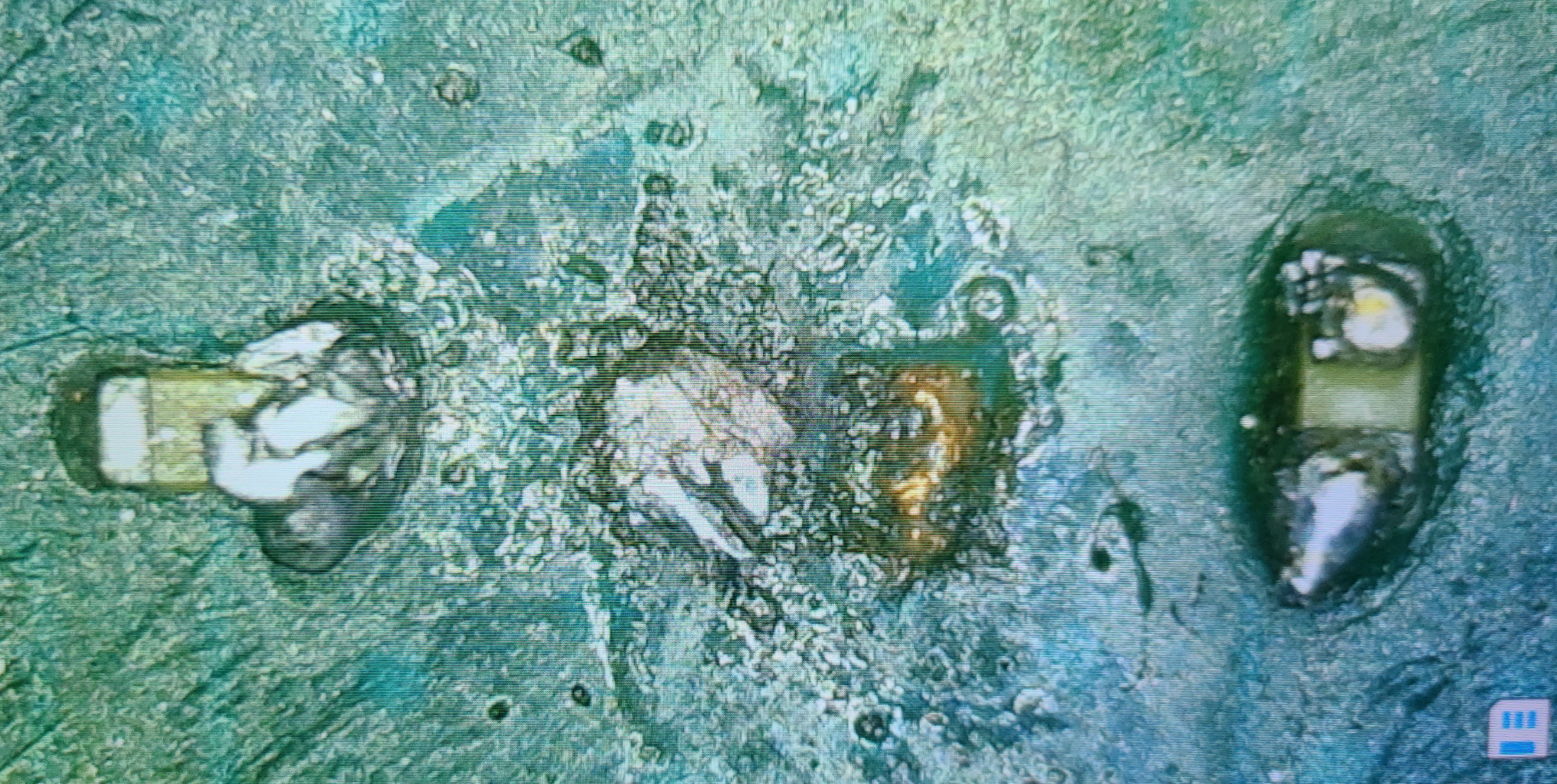
This happened during an attempt to install a picofly modchip (Failed miserably).

Is there a way to somehow solder the capacitor back on? Is it just enough with one pad?

I've heard that the modchip installation can still be done with one capacitor, but I don't really know.
1000046054.jpg
 
Which cap is this exactly?
With 1 pad only, the cap is not connected.
And it looks like that the pads might still be there.

Also, by looking at the result on the other caps, the iron tip isn't giving enough heat for the soldering.
This is also the reason why you rip the cap off in the first place.

Yes, there's also guide to use 1 cap shorted only for the modchip soldering.
 
  • Like
Reactions: splaca
Which cap is this exactly?
With 1 pad only, the cap is not connected.
And it looks like that the pads might still be there.

Also, by looking at the result on the other caps, the iron tip isn't giving enough heat for the soldering.
This is also the reason why you rip the cap off in the first place.

Yes, there's also guide to use 1 cap shorted only for the modchip soldering.
It's the SP2 Capacitor, I don't think there's any pad left on the right side, it was removed completely, there's just solder leftovers. I'm not sure if it's still fixable
I'll gladly appreciate if you could tell me where to find a guide to install the modchip with only one cap, just in case I can't fix this problem.
Thanks for your help!
 
Last edited by Kaboni,
It's the SP2 Capacitor, I don't think there's any pad left on the right side, it was removed completely, there's just solder leftovers. I'm not sure if it's still fixable
I'll gladly appreciate if you could tell me where to find a guide to install the modchip with only one cap, just in case I can't fix this problem.
Thanks for your help!
If I remember correctly, it should work just by ignoring this soldering point
Since these are power connections, 1 cap is enough, 2 caps for redundancy.

Also, before considering to ignore the cap, you can see if the ripped off pad is the ground pad.

If ground pad is ripped off, simply fix it by connecting the other end of the cap to a ground point by a jump wire. Matching it to the original soldering concept.
 
It's really hard to say without being able to see where the traces connect. Can you take another picture but zoomed out a bunch so I can see the little green line that leads away from the pad that got ripped off?

The basic idea for repairs like this is to add a thin rework wire (like those that are used for modchips) between the component and wherever the other side of the trace leads. Depending on how easy it is to tack a wire onto the thing at the other end of the trace, you may or may not be able to replace it.

As someone else said, some capacitors are redundant and used to add safety margins to the electronics. Some are absolutely required or the device will not work. But it's hard to say without seeing what it's connected to.
 
It's really hard to say without being able to see where the traces connect. Can you take another picture but zoomed out a bunch so I can see the little green line that leads away from the pad that got ripped off?

The basic idea for repairs like this is to add a thin rework wire (like those that are used for modchips) between the component and wherever the other side of the trace leads. Depending on how easy it is to tack a wire onto the thing at the other end of the trace, you may or may not be able to replace it.

As someone else said, some capacitors are redundant and used to add safety margins to the electronics. Some are absolutely required or the device will not work. But it's hard to say without seeing what it's connected to.
I'll attach some more pictures.
The Switch still works just fine without the SP2 capacitor.
 

Attachments

I'll attach some more pictures.
The Switch still works just fine without the SP2 capacitor.
Oof, looks like the trace is hidden inside the PCB, so it's not really possible to know how to repair it without the actual original schematic of the Switch PCB.

If your switch works without it, then I'd say cross your fingers and hope that cap was one of those "redundant safety" caps and not one of the "the Switch will eventually break without it" caps!

EDIT: Based on how they are laid out, I'm *pretty sure* those caps are probably not all needed. They are placed like standard decoupling caps for the nearby chip.
 
  • Like
Reactions: Kaboni
You can easily finish the installation with only one capacitor, in fact I personally always use only one point. And I'll tell you more, you can safely use a Flex V1 on Mariko/Lite/OLED without any problems.
connect the flex normally ignoring sp2 point S
 

Attachments

  • flex v2 pinout_r.jpg
    flex v2 pinout_r.jpg
    519.7 KB · Views: 151
  • Like
Reactions: Kaboni
Hey guys!

I really appreciate the help that you have lent me. Fortunately, I was able to install the modchip with one capacitor successfully. I did the same procedure, just ignoring the SP2 capacitor.

Thank you for everything! 👍🏻

View attachment Switch.jpg
 

Attachments

Last edited by Kaboni,

Site & Scene News

Popular threads in this forum