Hacking Hardware Picofly - a HWFLY switch modchip

ZXEdward

New Member
Newbie
Joined
May 3, 2023
Messages
2
Trophies
0
Age
34
XP
16
Country
China
Hello,gentalmen. I meet a problem after I welded RP2040.After pressing the power on button, the light of RP2040 will first turn blue, then turn red, and then turn off the switch to directly enter the original system. I changed the welding position from EMMC to motherboard and replaced the rubber wire with enameled wire,but the problem is still be not solved. Can anyone help to tell me what the problem is?
 

Attachments

  • VID_20230503_134637.mp4
    39.2 MB
  • 640746122.jpg
    640746122.jpg
    9.7 MB · Views: 64

QuiTim

Well-Known Member
Member
Joined
Mar 30, 2023
Messages
756
Trophies
0
XP
1,172
Country
Albania
Pretty clean. What did you use to cut the shield?
Post automatically merged:


I almost always get different results when closing it up, it's not until I triple-check the wires that it works. Starting to wonder if enamel wire is the way to go. What wire type do you prefer?
I usualy use ptfe, teflon, silicon when possible. With enamel everything looks like an unfinished job :)
Just got this yesterday https://a.aliexpress.com/_mO58PBe
I will give it a shot a post back.
 

abal1000x

Well-Known Member
Member
Joined
Jun 5, 2022
Messages
1,070
Trophies
0
XP
1,395
Country
Gaza Strip
Hello,gentalmen. I meet a problem after I welded RP2040.After pressing the power on button, the light of RP2040 will first turn blue, then turn red, and then turn off the switch to directly enter the original system. I changed the welding position from EMMC to motherboard and replaced the rubber wire with enameled wire,but the problem is still be not solved. Can anyone help to tell me what the problem is?
Seems like purple, emmc failed. Add the resistor value to around 100 ohm to minimalize the noise, might fix.
 

Modi

Well-Known Member
Newcomer
Joined
Mar 12, 2017
Messages
88
Trophies
0
Age
37
XP
364
Country
Poland
Correct and Clen installation Picofly on Oled 2022
 

Attachments

  • IMG_20230420_013429.jpg
    IMG_20230420_013429.jpg
    3.2 MB · Views: 61
  • IMG_20230419_204040.jpg
    IMG_20230419_204040.jpg
    1.6 MB · Views: 57
  • IMG_20230419_204022.jpg
    IMG_20230419_204022.jpg
    1.6 MB · Views: 50
  • IMG_20230420_013405.jpg
    IMG_20230420_013405.jpg
    1.8 MB · Views: 60
Last edited by Modi,

nico77

Well-Known Member
Member
Joined
Apr 6, 2023
Messages
160
Trophies
0
Age
33
XP
238
Country
Indonesia
Hello,gentalmen. I meet a problem after I welded RP2040.After pressing the power on button, the light of RP2040 will first turn blue, then turn red, and then turn off the switch to directly enter the original system. I changed the welding position from EMMC to motherboard and replaced the rubber wire with enameled wire,but the problem is still be not solved. Can anyone help to tell me what the problem is?
im in the process modding my lite, and i meet situation like you...
from your video, its not red color, looks like purple or pink . idk.

but i got same situation like you, which from blue > purple(maybe wasnt sure the color) , and lead to boot regular ofw.
but after that i resoldering my cables to resistor47, and i meet red led light=which make the screen only blackscreen, no boot to ofw. (after that i found my r47 soldering to rp2040 kinda bad joint/cracked, i use pinset and touch the R47 and it just fell off):whip:

since im only testing it, i havent cut my cables from D0,CMD,CLK to R47 rp2040, and the cable pretty long, soon prob ill cut to a properly measure length.
(prob in my situation bad joint on the point, also bad soldering/cold soldering/cracked solder)

im pause and waiting my uv light and new soldering iron to continue this process, last time im too careful with the D0,CMD,CLK point, im afraid if i broke the point. (for now i remove all wiring from the RP2040 and my lite still can boot to OFW with no problem)

can someone explain what red led light on rp2040 means ?
also which type cable better for the point ?
for now im using enamel 0.1mm for the point D0 CMD CLK
Post automatically merged:

Seems like purple, emmc failed. Add the resistor value to around 100 ohm to minimalize the noise, might fix.
i saw from the pico guide, they add double resistor R47+R47 total R94, is it gonna fix ?
for purple led indication problem ??
 
Last edited by nico77,

QuiTim

Well-Known Member
Member
Joined
Mar 30, 2023
Messages
756
Trophies
0
XP
1,172
Country
Albania
Another V2 install.
Used 38awg for data lines, 32awg for 3v3 and GND.
I also finally got my hands on 8342 QFN and I have to say, although the soldering is a bit more challenging the end result is more satisfying as it fits nicely and there is no need to cut anything.
Single mosfet worked like a charm.
 

Attachments

  • IMG_003.JPG
    IMG_003.JPG
    478.9 KB · Views: 66
  • IMG_004.jpg
    IMG_004.jpg
    339.5 KB · Views: 58
  • IMG_006.JPG
    IMG_006.JPG
    510.8 KB · Views: 55
  • IMG_007.JPG
    IMG_007.JPG
    459 KB · Views: 54

QuiTim

Well-Known Member
Member
Joined
Mar 30, 2023
Messages
756
Trophies
0
XP
1,172
Country
Albania
Added to cart. Please let us know.
This is the wire i just used (see post above).
Works great and it tins very well. Also I guess since it's single core it keeps the shape better when bent so you can route the wires more easily.
It's the yellow/orange one in this photo.
 

Attachments

  • IMG_007.JPG
    IMG_007.JPG
    459 KB · Views: 41
  • Like
Reactions: FreeLander

SkylerTakashi

Active Member
Newcomer
Joined
Mar 23, 2023
Messages
32
Trophies
0
Age
29
XP
95
Country
Iraq
Can i use these? 0.02mm cooper
Post automatically merged:

Can i use these? 0.02mm cooper
 

Attachments

  • FB_IMG_1683104430498.jpg
    FB_IMG_1683104430498.jpg
    26.7 KB · Views: 50

Takezo-San

Well-Known Member
Member
Joined
May 3, 2023
Messages
261
Trophies
0
Age
39
XP
349
Country
Seychelles
Another V2 install.
Used 38awg for data lines, 32awg for 3v3 and GND.
I also finally got my hands on 8342 QFN and I have to say, although the soldering is a bit more challenging the end result is more satisfying as it fits nicely and there is no need to cut anything.
Single mosfet worked like a charm.
So, in this singular MOSFET set up, are you running 2 wires from the drain to the 2 caps? Looks like one but its hard to tell but not sure how one wire would be possible!?
 

QuiTim

Well-Known Member
Member
Joined
Mar 30, 2023
Messages
756
Trophies
0
XP
1,172
Country
Albania
So, in this singular MOSFET set up, are you running 2 wires from the drain to the 2 caps? Looks like one but its hard to tell but not sure how one wire would be possible!?
Just one wire. It's not a problem, just bend the wire before soldering so you dont put alot of strain in the capacitors afterwards.
Alot of people did it, it works great (if you use single mosfet)
 

Attachments

  • Screenshot_20230421_163245_Gallery.jpg
    Screenshot_20230421_163245_Gallery.jpg
    1.1 MB · Views: 42
  • 20230418_193033[1] (1).jpg
    20230418_193033[1] (1).jpg
    1.6 MB · Views: 42
  • IMG_003.JPG
    IMG_003.JPG
    478.9 KB · Views: 41
  • Like
Reactions: susi91 and Modi

SQc04

Well-Known Member
Newcomer
Joined
Mar 23, 2023
Messages
99
Trophies
0
Age
21
XP
419
Country
China
1683111751421.png

1683125853460.jpeg

1683111807813.png

PICOFLY ИX module (verified)
https://github.com/SQc04/PICOFLY-X
Use easyeda PRO
https://easyeda.com/
The CPU cable will be released later
The resistor uses 0402 and is not recommended for novice welding
The circuit board is 0.8mm thick

V0.8.1+ supports jumpers, V1 V2 LITE OLED universal
 

Attachments

  • CENTER V0.8.1_b0002.zip
    124 KB · Views: 27
  • SCH_Schematic1.pdf
    316.4 KB · Views: 61
  • 1683125823256.jpeg
    1683125823256.jpeg
    1.9 MB · Views: 49
Last edited by SQc04,

Takezo-San

Well-Known Member
Member
Joined
May 3, 2023
Messages
261
Trophies
0
Age
39
XP
349
Country
Seychelles
Just one wire. It's not a problem, just bend the wire before soldering so you dont put alot of strain in the capacitors afterwards.
Alot of people did it, it works great (if you use single mosfet)
Oh I Seeeeeeeeeeeee. Those supplementary images made it a lot clearer. Basically we get a link from, cap-cap & then cap-drain, in one route (so to speak).
 

Modi

Well-Known Member
Newcomer
Joined
Mar 12, 2017
Messages
88
Trophies
0
Age
37
XP
364
Country
Poland
LOL what?

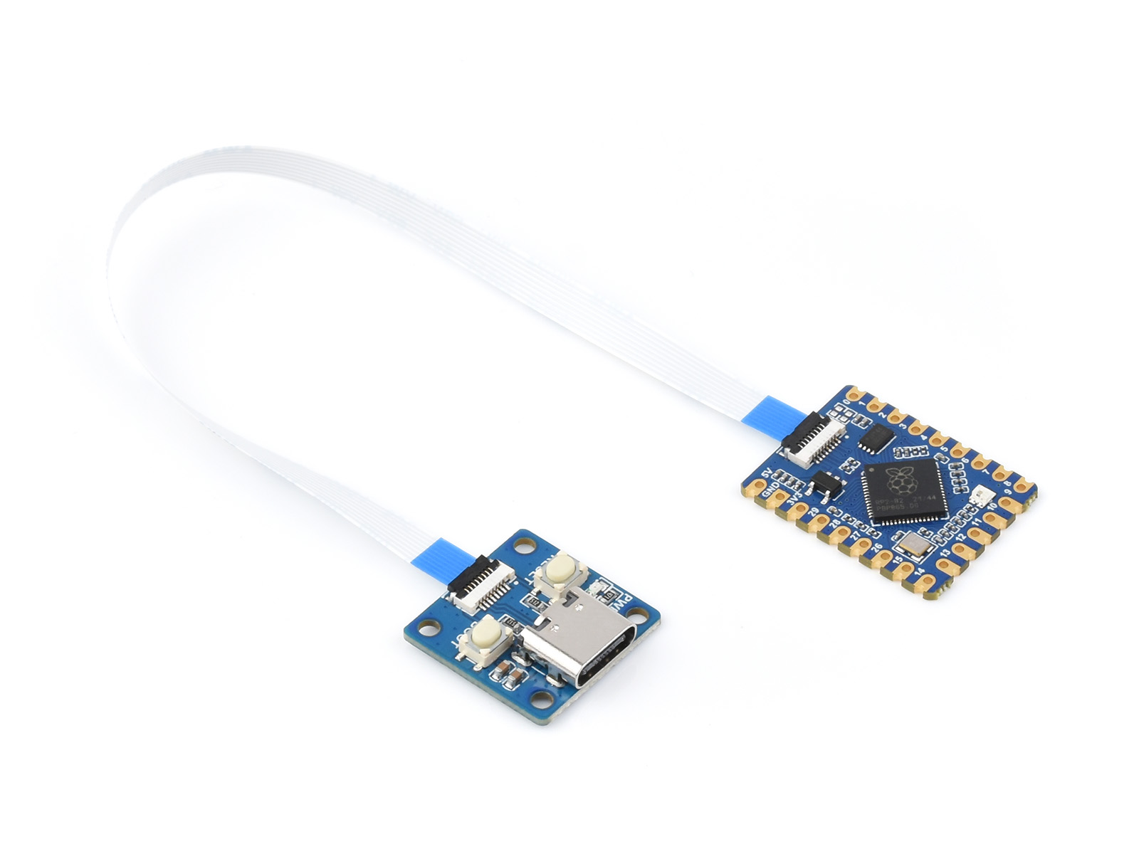
looks like Waveshare made a new "dev board" with detachable USB, resistors (47 ohm?) on pins 27, 28, 29, and "custom jumpers" on pins 24, 25.
https://www.waveshare.net/shop/RP2040-Tiny-Kit.htm

View attachment 368616
View attachment 368617
PICOFLY ИX module (verified)
Use easyeda PRO
https://easyeda.com/
The CPU cable will be released later
The resistor uses 0402 and is not recommended for novice welding

V0.8.1+ supports jumpers, V1 V2 LITE OLED universal
Great job mate. How fast they make this pcb?
 

Site & Scene News

Popular threads in this forum

General chit-chat
Help Users
    K3Nv2 @ K3Nv2: https://abyss-headphones.com/?utm_medium=paid&utm_source=fb&utm_id=120209532851760496&utm_content...