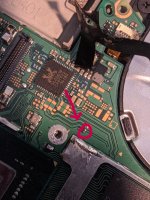
Switch OLED teardown V1/V2

HelloShitty

Well-Known Member
Member
Joined
Jan 16, 2022
Messages
252
Trophies
0
Age
124
XP
402
Country
Iran
The dat0 line for the sxcore has small issue (with initialize the emmc). A resistor might do the trick (as long as it is between the dat0 and the modchip)
Oh crap...
Are there any pictures where to place that resistor? People go for smd resistors? I only have 1202 format ones at han!
 

de9ed

Well-Known Member
Member
Joined
Oct 22, 2020
Messages
278
Trophies
0
Age
30
XP
919
Country
Canada
A timing or voltage issue?

What about the SX core with OLED? What is the reason to avoid?
speed of the transfer is the issue.
Oh crap...
Are there any pictures where to place that resistor? People go for smd resistors? I only have 1202 format ones at han!
any resistor work, just slap it on the modchip side or the dat0 adapter side
 
  • Like
Reactions: HelloShitty

zal16

Well-Known Member
Member
Joined
Oct 8, 2020
Messages
135
Trophies
0
Age
38
XP
656
Country
Brazil
Because I could get this one for like 100$. Way cheaper


What is it so hard about it?


I meant this one:
IMG_3373.jpg
in addition to installing the 6 wires (3.3v, GND, CLK, CMD, RST and DAT0) it is necessary to add 3 more wires, which go to the CPU ribbon. it is also necessary to cut a piece of the metal cover, because the sx core is too big
 

HelloShitty

Well-Known Member
Member
Joined
Jan 16, 2022
Messages
252
Trophies
0
Age
124
XP
402
Country
Iran
in addition to installing the 6 wires (3.3v, GND, CLK, CMD, RST and DAT0) it is necessary to add 3 more wires, which go to the CPU ribbon. it is also necessary to cut a piece of the metal cover, because the sx core is too big

Ok, I have this image. I think it is only missing GND
https://i.ibb.co/CPBrPB3/IMG-3547.jpg


I put a 100 ohm resistor and the glitch works so fast

But is this resistor in series between DAT0 underneath the NAND and the point on the other end (which is in the ribbon) ? Do you have an image so that I can make sure how the resistor should be placed?
 

Quezacotl

Well-Known Member
Newcomer
Joined
Aug 12, 2020
Messages
69
Trophies
0
Age
37
XP
235
Country
Finland
Ok, I have this image. I think it is only missing GND
https://i.ibb.co/CPBrPB3/IMG-3547.jpg


But is this resistor in series between DAT0 underneath the NAND and the point on the other end (which is in the ribbon) ? Do you have an image so that I can make sure how the resistor should be placed?
https://i.imgur.com/N9uNhFl.png
EDIT: This diagram i found on the net is not that good i think. The 3V3 point is permanent 3V3, as the one similar looking caps above is the one for when Switch is actually turned on. The other is that when i connect CPU3, it's like the modchip crashes. When it's disconnected, it's atleast doing something. I still haven't got my install to work.
 
Last edited by Quezacotl,

Quezacotl

Well-Known Member
Newcomer
Joined
Aug 12, 2020
Messages
69
Trophies
0
Age
37
XP
235
Country
Finland
Can anyone confirm the installation points? Look at the above diagram i posted.
And yes, i still cannot get it to work. The new 0.6.0 firmware diagnostic says i have problem with CPU connections.

-Does the 3V3 point need to be permanent like in the picture or the one cap above where you get 3V3 only when Switch is turned on?
-CPU3 when connected, i think it crashes the SX Core. Disconnected, and it actually does something. When reading the schematics and PCB photos, i see that CPU3 is only for Erista model. I have v2 adapter that has the CPU3(Erista point) connected to ground.
I would imagine that the SX core can see that it's grounded if it's connected, and act according, but is it supposed to? Afterall, everything is about focusing on OLED, especially on spacecraft firmwares.
-I have noticed that the resistor(i have 22R) on DAT0 line actually allows the Switch to boot past Nintendo-logo to OFW. Without it, it always hangs after Nintendo-logo.
-Do i need the SD card at all? Can i confirm that the mod works without SD? There's sdloader.enc and hwfly_toolbox.bin, but i don't know if their required in the troubleshooting.
-Anything else worth mentioning?
 

doom95

Well-Known Member
Member
Joined
Aug 12, 2019
Messages
303
Trophies
0
Age
24
XP
785
Country
Netherlands
The diagram is wrong. Sthetix updated it on his github. Use the 3v3 point on the larger caps.

Even without SD card, on a good install you get a green light, and the OLED display will tell you that you need to insert an sdcard. From that screen you can boot into OFW by pressing VOL+/VOL- simultaneously.
 

doom95

Well-Known Member
Member
Joined
Aug 12, 2019
Messages
303
Trophies
0
Age
24
XP
785
Country
Netherlands
I wouldn't use the wrong modchip for an OLED. Install is hard enough as-is.

But if you insist, you can trick the firmware into thinking it's an sx-lite by pulling up pin 39 on the microcontroller to 3v3. Currently it will have a resistor to ground, that's how the firmware knows the type of board it is. That will trigger oled-compatible behavior.
CPU point 3 is not necessary.
 

Shadow_The_Hedgehog82

Well-Known Member
Member
Joined
Jul 22, 2018
Messages
282
Trophies
0
Age
42
XP
949
Country
Australia
Think i killed my oled. I install the oled chip then it was booting to stock os, realised I forgot point A. I went back and tried to solder that, the little component there got sucked into my iron I tried booting anyway but now it just boots to a purple screen.

I removed the chip and ribbon and it still boots to purple.

Anyone know what the component is so i can buy a repalcement?
 

Attachments

  • resistor or something.jpg
    resistor or something.jpg
    1.5 MB · Views: 192

Quezacotl

Well-Known Member
Newcomer
Joined
Aug 12, 2020
Messages
69
Trophies
0
Age
37
XP
235
Country
Finland
Think i killed my oled. I install the oled chip then it was booting to stock os, realised I forgot point A. I went back and tried to solder that, the little component there got sucked into my iron I tried booting anyway but now it just boots to a purple screen.

I removed the chip and ribbon and it still boots to purple.

Anyone know what the component is so i can buy a repalcement?
I'm measuring it as 4k7 resistor.
 

Quezacotl

Well-Known Member
Newcomer
Joined
Aug 12, 2020
Messages
69
Trophies
0
Age
37
XP
235
Country
Finland
I wouldn't use the wrong modchip for an OLED. Install is hard enough as-is.

But if you insist, you can trick the firmware into thinking it's an sx-lite by pulling up pin 39 on the microcontroller to 3v3. Currently it will have a resistor to ground, that's how the firmware knows the type of board it is. That will trigger oled-compatible behavior.
CPU point 3 is not necessary.
That really changed the behavior a little. Now my Switch does is blinking green, blinking purple, solid white. Before that it immediately turned solid white.
What is actually a OLED compatible behavior? What it actually does?
 

doom95

Well-Known Member
Member
Joined
Aug 12, 2019
Messages
303
Trophies
0
Age
24
XP
785
Country
Netherlands
wouldn't be too crazy to hand it off at this point. these are clear indicators you should start treading very carefully on this board before it reaches a state where it becomes unservicable
 

Site & Scene News

Popular threads in this forum

General chit-chat
Help Users
  • No one is chatting at the moment.
    Veho @ Veho: Wow, only $700?