You are using an out of date browser. It may not display this or other websites correctly.
You should upgrade or use an alternative browser.
You should upgrade or use an alternative browser.
Picofly AIO Thread
- Thread starter Adran_Marit
- Start date
- Views 534,979
- Replies 3,369
- Likes 60
Yes.. thats normal duration.This one was delaying only during several first boots, but after that, It started to boot fairly quickly enough.
View attachment 392004
Its normal that the first boot take a bit longer , after a few boots it gets fasterThis one was delaying only during several first boots, but after that, It started to boot fairly quickly enough.
View attachment 392004
- Joined
- Sep 2, 2020
- Messages
- 1,311
- Trophies
- 0
- Age
- 39
- Location
- TORONTO
- Website
- form.jotform.com
- XP
- 2,251
- Country

Did you try undervoltage hack?Anyone know a fix for mariko slow boot times? X_X sometimes it takes 1 minute to boot on some consoles
https://gbatemp.net/threads/picofly-a-hwfly-switch-modchip.622701/post-10090767
I am flashing firmware on picofly wondershare device.
Here is what I am doing-
1 Press boot menu and simultaneously plug usb c end into USB port. (No led response, PC detects portable device in explorer)
2 Drag firmware 2.74.uf file into the rp2040 device folder (no led response on the RP2040 board is observed)
3 Explorer window automatically closes with no change in led status on RP2040
4 On reinserting without pressing boot button, its blinking long blue followed by short green blinks continuously.
My question is,
1 How can I know that I have successfully flashed firmware?
2 Is there any way to check firmware on RP2040?
Guide mention that it should blink red for successful flash and even first page is not clear about the procedure.
Please be patient, no need to double post.. I already reply on other thread.I am flashing firmware on picofly wondershare device.
Here is what I am doing-
1 Press boot menu and simultaneously plug usb c end into USB port. (No led response, PC detects portable device in explorer)
2 Drag firmware 2.74.uf file into the rp2040 device folder (no led response on the RP2040 board is observed)
3 Explorer window automatically closes with no change in led status on RP2040
4 On reinserting without pressing boot button, its blinking long blue followed by short green blinks continuously.
My question is,
1 How can I know that I have successfully flashed firmware?
2 Is there any way to check firmware on RP2040?
Guide mention that it should blink red for successful flash and even first page is not clear about the procedure.
Thanks for suggesting this.Yes. most of us are doing 100/100/47 by now since it's more likely to work well
I now replace my resistors as you suggested without bothering to see if 47/47/47 would work first.
Zero issues

I followed up on the suggestion from @QuiTim to use 0201 resistors. I used very fine solder paste applied with a sewing needle and hot air.
It's very satisfying to see them snap into place as the paste melts.
Attachments
Last edited by RedFawkes,
Hi! Hope you can help me please.
I have a Nintendo switch OLED with a picofly chip installed, it was working fine but today y reset the console and now it's booting into OFW, no hetake or "No SD CARD" screen, just OFW auto
What I can do? I attached a video for the picofly LEDs indicators.
I have a Nintendo switch OLED with a picofly chip installed, it was working fine but today y reset the console and now it's booting into OFW, no hetake or "No SD CARD" screen, just OFW auto
What I can do? I attached a video for the picofly LEDs indicators.
Hi! Hope you can help me please.
I have a Nintendo switch OLED with a picofly chip installed, it was working fine but today y reset the console and now it's booting into OFW, no hetake or "No SD CARD" screen, just OFW auto
What I can do? I attached a video for the picofly LEDs indicators.
Its a DAT0 not conected error.
First (Hope) : unsolder the D0 wire from pico, check the wire continuity with ground, if still there then try to resolder it again to pico and try.
Last Thing (most likely) :
Pull out the mobo. then resolder/refix the DAT0 adapter.
I see that the guide says for that led code = * = * that means emmc write error?, should I remove the DAT0 adapter?Its a DAT0 not conected error.
First (Hope) : unsolder the D0 wire from pico, check the wire continuity with ground, if still there then try to resolder it again to pico and try.
Last Thing (most likely) :
Pull out the mobo. then resolder/refix the DAT0 adapter.
Post automatically merged:
I solved that idk why but I have to move the D0 adapter (Nintendo switch OLED) and that's all :/ thanks for all m8'sI see that the guide says for that led code = * = * that means emmc write error?, should I remove the DAT0 adapter?
Last edited by JB260895,
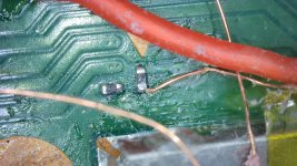
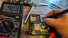
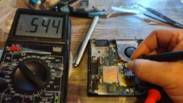
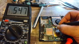
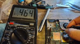
Um . Did an oopsie? I have no ideea if by mistake i took out that resistor or it never was there. I searched for it everywhere and it seems like it went into 9th realm or something. Its nowhere to be found.
i know something is different on the rst point on v1/v2 on some of them. BUT i really dont remember if this one had the resistor .
This console is a V2. Excuse the quality and flux but i just cleared it a little just to not shine too much.

So i did a little bit of looking around it it looks like this resistor is for a test point. In theory i should be able to snatch this one, move it below the RST point, and use the CMD on the NAND point righhhhht????... I dont have a donor board and i dont have these resistors in my possesion.

Update on this part: Found out that this is a REALLY bad ideea.These are pullup resistors between 1v and cmd/rst. (Special thanks to @abal1000x for educating me)
Also from what he told me, you could also put a 4.9k ohm resistor. I have not tryed that yet and im scared? Im still leaning on putting a 4.7k . If however you find yourself in this situation, and have a spare picofly, you can steal a 4.9k(or 5k im not sure,my multimeter is not great. It also reads the 4.7k to 4.6k) from near usb C (i think they are the same size aka 0201)

I found the 4.7k resistor and i struggled to solder it back on. Ended up ripping the pads FROM underneath THE RESISTOR (not the board) so now i cant connect it properly from underneath the resistors. I think i will have to connect it from the sides with jumper wires........... so that s that.............. What i tought about doing from the first place was to use hot air and just let surface tension do its job but then i looked at that plastic emmc connector near it and i went "nope".
Ill do this tomorrow since now im on 24h of no sleep >.>

i know something is different on the rst point on v1/v2 on some of them. BUT i really dont remember if this one had the resistor .
This console is a V2. Excuse the quality and flux but i just cleared it a little just to not shine too much.
So i did a little bit of looking around it it looks like this resistor is for a test point. In theory i should be able to snatch this one, move it below the RST point, and use the CMD on the NAND point righhhhht????... I dont have a donor board and i dont have these resistors in my possesion.
Update on this part: Found out that this is a REALLY bad ideea.These are pullup resistors between 1v and cmd/rst. (Special thanks to @abal1000x for educating me)
Also from what he told me, you could also put a 4.9k ohm resistor. I have not tryed that yet and im scared? Im still leaning on putting a 4.7k . If however you find yourself in this situation, and have a spare picofly, you can steal a 4.9k(or 5k im not sure,my multimeter is not great. It also reads the 4.7k to 4.6k) from near usb C (i think they are the same size aka 0201)
I found the 4.7k resistor and i struggled to solder it back on. Ended up ripping the pads FROM underneath THE RESISTOR (not the board) so now i cant connect it properly from underneath the resistors. I think i will have to connect it from the sides with jumper wires........... so that s that.............. What i tought about doing from the first place was to use hot air and just let surface tension do its job but then i looked at that plastic emmc connector near it and i went "nope".
Ill do this tomorrow since now im on 24h of no sleep >.>
Last edited by Crung,
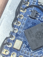
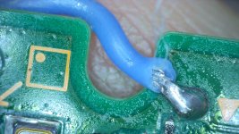
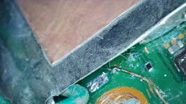
Alright, this has me stumped. I believe this is the no RST error, but all my connections are good.
View attachment 393365View attachment 393366View attachment 393367View attachment 393355View attachment 393356View attachment 393357View attachment 393358View attachment 393359View attachment 393360View attachment 393361View attachment 393362
It still boots to OFW. It is fully factory and never set up. I am not sure if that will affect it. Any ideas?
what resistors do you have on dat0 cmd and clk?
0805 470 resistors (47ohm +/-5%)what resistors do you have on dat0 cmd and clk?
Could it be because it is straight out of the box without updating or setting up?
Last edited by HacksNDrones,
you need 2x470 (47 ohms ) resistors on DAT0 and CMD0805 470 resistors (47ohm +/-5%)
Could it be because it is straight out of the box without updating or setting up?
also does that board fit with the usb c port still on?
Last edited by Crung,
- Joined
- Sep 2, 2020
- Messages
- 1,311
- Trophies
- 0
- Age
- 39
- Location
- TORONTO
- Website
- form.jotform.com
- XP
- 2,251
- Country

Alright, this has me stumped. I believe this is the no RST error, but all my connections are good.
View attachment 393365View attachment 393366View attachment 393367View attachment 393355View attachment 393356View attachment 393357View attachment 393359View attachment 393360View attachment 393361View attachment 393362
It still boots to OFW. It is fully factory and never set up. I am not sure if that will affect it. Any ideas?
triple check where you take the 3.3v from
Got a wierd V2. So i lost the 4.7k resistor near RST. Replaced it with a 5k resistor as adviced (that s what i had on my hands).
Went ahead and completed the job. Then it worked.After a couple of boots, i get ** check RST. After some digging out, i think i found the problem. CLK wire (enammeled wire) got really hot while soldering and lost its insulation, and was shorting the RST on picofly? Went ahead, fixed the job, put solder mask on it to keep it nice.
Also did i2c low voltage on it since it had terrible boot times. Now its fast. (but i dont know if the low voltage technique fixed the boot times, or the fact that i fixed the CLK possibly shorting the RST)
All good , did a lot of power ons. Went ahead and proceeded with securing everything into solder mask. And when i tought that everything was nice and fixed, i got ** RST again X_X one time. But now i cant get it to do the error again. WHAT THE FFFFFFF
Edit. After partial reassemble, it get ** rst perma
Update 2: it turns out i did a pretty shitty job of resoldering the resistor. i did not have any low melt solder or paste. It was somehow not properly connected on 1 pad ,however making contact. I resoldered that point and it seemes it went away for god? We ll see.
Last edited by Crung,
That was my error as pointed out on by someone on discord. Now I have a mosfet error. I am going to try the back of the mobo version.triple check where you take the 3.3v from
Similar threads
- Replies
- 10
- Views
- 2K
- Replies
- 8
- Views
- 3K
- Replies
- 3
- Views
- 759
- Replies
- 10
- Views
- 2K
- Replies
- 1
- Views
- 2K
Site & Scene News
New Hot Discussed
-
-
29K views
New static recompiler tool N64Recomp aims to seamlessly modernize N64 games
As each year passes, retro games become harder and harder to play, as the physical media begins to fall apart and becomes more difficult and expensive to obtain. The... -
26K views
Nintendo officially confirms Switch successor console, announces Nintendo Direct for next month
While rumors had been floating about rampantly as to the future plans of Nintendo, the President of the company, Shuntaro Furukawa, made a brief statement confirming... -
23K views
TheFloW releases new PPPwn kernel exploit for PS4, works on firmware 11.00
TheFlow has done it again--a new kernel exploit has been released for PlayStation 4 consoles. This latest exploit is called PPPwn, and works on PlayStation 4 systems... -
22K views
Nintendo takes down Gmod content from Steam's Workshop
Nintendo might just as well be a law firm more than a videogame company at this point in time, since they have yet again issued their now almost trademarked usual...by ShadowOne333 129 -
22K views
Name the Switch successor: what should Nintendo call its new console?
Nintendo has officially announced that a successor to the beloved Switch console is on the horizon. As we eagerly anticipate what innovations this new device will... -
17K views
A prototype of the original "The Legend of Zelda" for NES has been found and preserved
Another video game prototype has been found and preserved, and this time, it's none other than the game that spawned an entire franchise beloved by many, the very...by ShadowOne333 32 -
14K views
DOOM has been ported to the retro game console in Persona 5 Royal
DOOM is well-known for being ported to basically every device with some kind of input, and that list now includes the old retro game console in Persona 5 Royal... -
12K views
AYANEO officially launches the Pocket S, its next-generation Android gaming handheld
Earlier this year, AYANEO revealed details of its next Android-based gaming handheld, the AYANEO Pocket S. However, the actual launch of the device was unknown; that... -
11K views
Delta emulator for iOS will support iPad devices in its next update
With just a couple weeks after its initial release in the App Store, the Delta emulator for iOS was received with great success, after Apple loosened up its rules in...by ShadowOne333 35 -
11K views
Anbernic reveals the RG35XXSP, a GBA SP-inspired retro handheld
Retro handheld manufacturer Anbernic has revealed its first clamshell device: the Anbernic RG35XXSP. As the suffix indicates, this handheld's design is inspired by...
-
-
-
298 replies
Name the Switch successor: what should Nintendo call its new console?
Nintendo has officially announced that a successor to the beloved Switch console is on the horizon. As we eagerly anticipate what innovations this new device will...by Costello -
232 replies
Nintendo officially confirms Switch successor console, announces Nintendo Direct for next month
While rumors had been floating about rampantly as to the future plans of Nintendo, the President of the company, Shuntaro Furukawa, made a brief statement confirming...by Chary -
133 replies
New static recompiler tool N64Recomp aims to seamlessly modernize N64 games
As each year passes, retro games become harder and harder to play, as the physical media begins to fall apart and becomes more difficult and expensive to obtain. The...by Chary -
129 replies
Nintendo takes down Gmod content from Steam's Workshop
Nintendo might just as well be a law firm more than a videogame company at this point in time, since they have yet again issued their now almost trademarked usual...by ShadowOne333 -
96 replies
Ubisoft reveals 'Assassin's Creed Shadows' which is set to launch later this year
Ubisoft has today officially revealed the next installment in the Assassin's Creed franchise: Assassin's Creed Shadows. This entry is set in late Sengoku-era Japan...by Prans -
87 replies
The Kingdom Hearts games are coming to Steam
After a little more than three years of exclusivity with the Epic Games Store, Square Enix has decided to bring their beloved Kingdom Hearts franchise to Steam. The...by Chary -
80 replies
TheFloW releases new PPPwn kernel exploit for PS4, works on firmware 11.00
TheFlow has done it again--a new kernel exploit has been released for PlayStation 4 consoles. This latest exploit is called PPPwn, and works on PlayStation 4 systems...by Chary -
78 replies
"Nintendo World Championships: NES Edition", a new NES Remix-like game, launching July 18th
After rumour got out about an upcoming NES Edition release for the famed Nintendo World Championships, Nintendo has officially unveiled the new game, titled "Nintendo...by ShadowOne333 -
71 replies
DOOM has been ported to the retro game console in Persona 5 Royal
DOOM is well-known for being ported to basically every device with some kind of input, and that list now includes the old retro game console in Persona 5 Royal...by relauby -
65 replies
Microsoft is closing down several gaming studios, including Tango Gameworks and Arkane Austin
The number of layoffs and cuts in the videogame industry sadly continue to grow, with the latest huge layoffs coming from Microsoft, due to what MIcrosoft calls a...by ShadowOne333
-
Popular threads in this forum
General chit-chat
- No one is chatting at the moment.
-
-
 @
K3Nv2:
But could be bad for people with lower speeds but how many mbs would it really need to detect a button press
 -
-
-
-
-
-
-
-
-
-
-
-
-
-
-
-
-
-
-
-
-
 @
The Real Jdbye:
https://www.amazon.com/Tentacles-Made-Gay-Hunter-Fox-ebook/dp/B00M0VCUPK let's be real, who isn't at least a little gay for tentacles though?
 -
-


