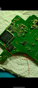
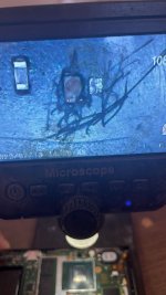
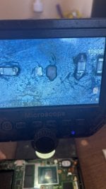
For me, no success, i was trying to modify the hekate, but just get the "basic" version "working", but have the screen "bugged", so just "works" to reboot into rcm, or try to boot without checking the fusses, that can be made with a modded version of ums-loaderAbout the emmc corruption, @abal1000x seems the most knowledgeable in emmc stuff (sorry if I'm wrong, haven't been active here for long).
Even with dat0/1 short shouldn't hekate boot? I have the bad adapter, is it even worth it to remove it and cut the lobe from the dat1 side like you suggest if I have constant sucessful glitch? I can mount GPP, not sure if there's any way to verify if there's boot0/1 corruption using ums-loader.
Btw I'm using @floxcap version of ums-loader that has some changes to the code to test emmc and it says my mmc is ok.
Is there any way to test DRAM? Any way to just confirm that it is the problem?
@floxcap did you ever made the changes to ums-loader to test DRAM read/write?
@HackMan37 any luck modding ums-loader?
Thanks in advance!
You are using an out of date browser. It may not display this or other websites correctly.
You should upgrade or use an alternative browser.
You should upgrade or use an alternative browser.
Staff Posts
Recent threadmarks
sharing files
Important Posts
Recent threadmarks
FirmwaresThx, but whats the purpose?Search on github, its hekate whose created it.
View attachment 383102
Theres also on atmosphere -> fusee
View attachment 383101
Required to properly wake up the NS from sleep. When you use emuNAND, CPU fuses might become desynced with your bootloader. This file contains all the information to boot the CPU.Thx, but whats the purpose?
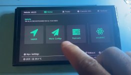
When you update the original system, it is necessary to update this file by booting to OFW using hekate menu (not the "Reboot/OFW" but the another one, "More Configs" -> "Full Stock" in some famous sets)
Not too sure.Thx, but whats the purpose?
You might open new thread, or goes to hekate thread or github issue, and asking them for the purposes.
I read the code slightly (not seriously read), its about checking the fuse count, if the fuse count incorrect, the sleep wont work. So its kind of patching that, so the sleep still working.
I might wrong, you need to ask in their issue, to be sure.
Thanks!Required to properly wake up the NS from sleep. When you use emuNAND, CPU fuses might become desynced with your bootloader. This file contains all the information to boot the CPU.
When you update the original system, it is necessary to update this file by booting to OFW using hekate menu (not the "Reboot/OFW" but the another one, "More Configs" -> "Full Stock" in some famous sets)
You mean via
fss0=atmosphere/package3
stock=1
emummc_force_disable=1
in hekate config?
YesThanks!
You mean via
fss0=atmosphere/package3
stock=1
emummc_force_disable=1
in hekate config?
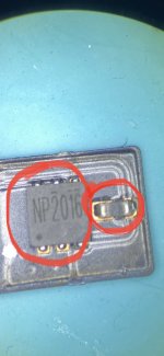
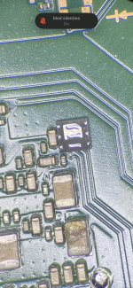
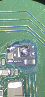
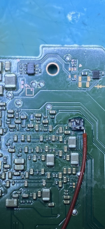
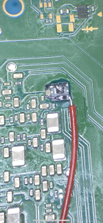
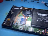
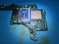
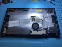
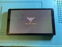
Picofly soldered on Oled with mosfet on the back pcb. I took the mosfet from the defective connection ribbon of one Hwfly. I used some thin copper wire to solder on the capacitor and loaded it with more tin. Excellent glitch time.
Attachments
-
 1.jpeg200.3 KB · Views: 57
 -
 2.png7.2 MB · Views: 44
 -
 3.png6.2 MB · Views: 54
 -
 4.png6.4 MB · Views: 52
 -
 5.png6.9 MB · Views: 50
 -
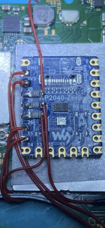 6.png6.9 MB · Views: 47
 -
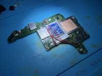 39D3FE8F-18BF-4975-9DF1-40BC28763496.jpeg1.8 MB · Views: 48
 -
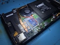 85276701-4828-4570-B041-0629AAD15B38.jpeg2.9 MB · Views: 44
 -
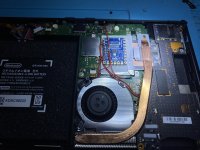 B99A628D-1EE2-4E01-BD24-E727FD269683.jpeg3.1 MB · Views: 42
 -
 C4E26972-B35A-435C-828A-95D7290C64FC.jpeg2.8 MB · Views: 44
 -
 E7A799DA-B6E8-4362-8A0E-F690BF9C9644.jpeg2.1 MB · Views: 46
 -
 F7C9062C-EF09-4D28-986C-2FD844A181DC.jpeg2.5 MB · Views: 42
 -
 65F6AC96-D9AB-44EE-899D-B066D6EE4DBB.jpeg2.5 MB · Views: 37
 -
 hjjjhhj.jpg155 KB · Views: 31
 -
 ytytytyt.jpg151.9 KB · Views: 43
Last edited by FXDX,
Hi, good evening,
I'm new here in forum and i need your help.
I bought a very cheap Switch V2, when i was unlocking, I realized that it already had passed in other hands.
The Caps and Pads of the positive points SP1 and SP2 on the APU was removed.
Is there a way of recover these Pads or any other alternative points to unlock it???
Looking this topic I saw it's possible to install MOSFET on the OLED's back. Can i install it on V2?
Thanks for your attention.
See the images bellow.
Attachments
Last edited by revsgrow,
Hi, good evening,
I'm new here in forum and i need your help.
I bought a very cheap Switch V2, when i was unlocking, I realized that it already had passed in other hands.
The Caps and Pads of the positive points SP1 and SP2 on the APU was removed.
Is there a way of recover these Pads or any other alternative points to unlock it???
Looking this topic I saw it's possible to install MOSFET on the OLED's back. Can i install it on V2?
Thanks for your attention.
See the images bellow.
Nice work. What's your glitch time?Picofly soldered on Oled with mosfet on the back pcb. I took the mosfet from the defective connection ribbon of one Hwfly. I used some thin copper wire to solder on the capacitor and loaded it with more tin. Excellent glitch time.
Excuse me, but doing what was indicated I was not successful.
Am I using a different firmware than the one indicated for this installation?
I'm using firmware 2.73.
Thanks!!
Am I using a different firmware than the one indicated for this installation?
I'm using firmware 2.73.
Thanks!!
In summary, majority problem is the installation.Excuse me, but doing what was indicated I was not successful.
Am I using a different firmware than the one indicated for this installation?
I'm using firmware 2.73.
Thanks!!
Show us the video of the error light.
Some picture of the works, the mosfet, dat0, clk, cmd, reset, rp2040 board, so we could help to confirm it.
the error code shown when starting the switch is ==* (two long pulses and one short pulse)In summary, majority problem is the installation.
Show us the video of the error light.
Some picture of the works, the mosfet, dat0, clk, cmd, reset, rp2040 board, so we could help to confirm it.
According to the error code, I mean this is not mosfet!
but I redid the installation twice and was unsuccessful.
Remembering that my APU does not have SP2 or SP2 points.
So I'm looking for alternative points to solder the mosfet and pull the GATE to the picofly.
Tomorrow I will send the pictures.
Thanks.
Boots to hekate in less than a second. Sysmmc/atmosphere boot is normal, no lag.Nice work. What's your glitch time?
I was checking the installation scheme image and realized where I could be going wrong.In summary, majority problem is the installation.
Show us the video of the error light.
Some picture of the works, the mosfet, dat0, clk, cmd, reset, rp2040 board, so we could help to confirm it.
I realized that from the Source to the Gate of the mosfet IR8242 there is a capacitor/resistor (I couldn't identify) that I didn't put in my installation.
Could you tell me what component this is, what is its value and where can I find it?
thanks!
I don't quite understand with your meaning.I was checking the installation scheme image and realized where I could be going wrong.
I realized that from the Source to the Gate of the mosfet IR8242 there is a capacitor/resistor (I couldn't identify) that I didn't put in my installation.
Could you tell me what component this is, what is its value and where can I find it?
thanks!
If you mean the pulldown resistor, its not mandatory.
The glitch will work without the pulldown resistor.
Picofly soldered on Oled with mosfet on the back pcb. I took the mosfet from the defective connection ribbon of one Hwfly. I used some thin copper wire to solder on the capacitor and loaded it with more tin. Excellent glitch time.
I realize that my installation is not the same as this one.I don't quite understand with your meaning.
If you mean the pulldown resistor, its not mandatory.
The glitch will work without the pulldown resistor.
Because this is missing a component that is connected from the source to the gate of the mosfet.
I would like to know what component this is, along with the value so that I can put it in my installation.
remembering that I'm not using the NP2040 mosfet, I'm using the IR8242.
That is pull down resistor, its not mandatory.I realize that my installation is not the same as this one.
Because this is missing a component that is connected from the source to the gate of the mosfet.
I would like to know what component this is, along with the value so that I can put it in my installation.
remembering that I'm not using the NP2040 mosfet, I'm using the IR8242.
Without it the glitching still works.
Take a photo on your works, if there are probable mistakes we might point it out.
Exactly as @twins333 said, the glitch time is excellent to hekate in less than a second and Sysmmc/atmosphere boot is normal, no lagNice work. What's your glitch time?

Similar threads
- Replies
- 4
- Views
- 2K
- Replies
- 2
- Views
- 607
- Replies
- 42
- Views
- 7K
Site & Scene News
New Hot Discussed
-
-
31K views
Nintendo Switch firmware update 18.0.1 has been released
A new Nintendo Switch firmware update is here. System software version 18.0.1 has been released. This update offers the typical stability features as all other... -
27K views
New static recompiler tool N64Recomp aims to seamlessly modernize N64 games
As each year passes, retro games become harder and harder to play, as the physical media begins to fall apart and becomes more difficult and expensive to obtain. The... -
25K views
Nintendo officially confirms Switch successor console, announces Nintendo Direct for next month
While rumors had been floating about rampantly as to the future plans of Nintendo, the President of the company, Shuntaro Furukawa, made a brief statement confirming... -
23K views
TheFloW releases new PPPwn kernel exploit for PS4, works on firmware 11.00
TheFlow has done it again--a new kernel exploit has been released for PlayStation 4 consoles. This latest exploit is called PPPwn, and works on PlayStation 4 systems... -
21K views
Nintendo takes down Gmod content from Steam's Workshop
Nintendo might just as well be a law firm more than a videogame company at this point in time, since they have yet again issued their now almost trademarked usual...by ShadowOne333 129 -
20K views
Name the Switch successor: what should Nintendo call its new console?
Nintendo has officially announced that a successor to the beloved Switch console is on the horizon. As we eagerly anticipate what innovations this new device will... -
17K views
A prototype of the original "The Legend of Zelda" for NES has been found and preserved
Another video game prototype has been found and preserved, and this time, it's none other than the game that spawned an entire franchise beloved by many, the very...by ShadowOne333 32 -
13K views
DOOM has been ported to the retro game console in Persona 5 Royal
DOOM is well-known for being ported to basically every device with some kind of input, and that list now includes the old retro game console in Persona 5 Royal... -
13K views
Nintendo Switch Online adds two more Nintendo 64 titles to its classic library
Two classic titles join the Nintendo Switch Online Expansion Pack game lineup. Available starting April 24th will be the motorcycle racing game Extreme G and another... -
12K views
AYANEO officially launches the Pocket S, its next-generation Android gaming handheld
Earlier this year, AYANEO revealed details of its next Android-based gaming handheld, the AYANEO Pocket S. However, the actual launch of the device was unknown; that...
-
-
-
289 replies
Name the Switch successor: what should Nintendo call its new console?
Nintendo has officially announced that a successor to the beloved Switch console is on the horizon. As we eagerly anticipate what innovations this new device will...by Costello -
232 replies
Nintendo officially confirms Switch successor console, announces Nintendo Direct for next month
While rumors had been floating about rampantly as to the future plans of Nintendo, the President of the company, Shuntaro Furukawa, made a brief statement confirming...by Chary -
133 replies
New static recompiler tool N64Recomp aims to seamlessly modernize N64 games
As each year passes, retro games become harder and harder to play, as the physical media begins to fall apart and becomes more difficult and expensive to obtain. The...by Chary -
129 replies
Nintendo takes down Gmod content from Steam's Workshop
Nintendo might just as well be a law firm more than a videogame company at this point in time, since they have yet again issued their now almost trademarked usual...by ShadowOne333 -
93 replies
Ubisoft reveals 'Assassin's Creed Shadows' which is set to launch later this year
Ubisoft has today officially revealed the next installment in the Assassin's Creed franchise: Assassin's Creed Shadows. This entry is set in late Sengoku-era Japan...by Prans -
82 replies
Nintendo Switch firmware update 18.0.1 has been released
A new Nintendo Switch firmware update is here. System software version 18.0.1 has been released. This update offers the typical stability features as all other...by Chary -
80 replies
TheFloW releases new PPPwn kernel exploit for PS4, works on firmware 11.00
TheFlow has done it again--a new kernel exploit has been released for PlayStation 4 consoles. This latest exploit is called PPPwn, and works on PlayStation 4 systems...by Chary -
78 replies
"Nintendo World Championships: NES Edition", a new NES Remix-like game, launching July 18th
After rumour got out about an upcoming NES Edition release for the famed Nintendo World Championships, Nintendo has officially unveiled the new game, titled "Nintendo...by ShadowOne333 -
71 replies
The Kingdom Hearts games are coming to Steam
After a little more than three years of exclusivity with the Epic Games Store, Square Enix has decided to bring their beloved Kingdom Hearts franchise to Steam. The...by Chary -
71 replies
DOOM has been ported to the retro game console in Persona 5 Royal
DOOM is well-known for being ported to basically every device with some kind of input, and that list now includes the old retro game console in Persona 5 Royal...by relauby
-
Popular threads in this forum
General chit-chat
-
 Xdqwerty
Loading…what are you looking at?
 -
 AncientBoi
Loading…
-
-
-
-
-
 @
SylverReZ:
@Xdqwerty, Desktop buddies existed long before Bonzi Buddy. Its quite similar but without the spyware. It came free with a box of cereal.+1
@
SylverReZ:
@Xdqwerty, Desktop buddies existed long before Bonzi Buddy. Its quite similar but without the spyware. It came free with a box of cereal.+1 -
-
-
 @
Xdqwerty:
@SylverReZ, I recall my aunt's PC with Windows xp had some of the characters from the search tool+1
@
Xdqwerty:
@SylverReZ, I recall my aunt's PC with Windows xp had some of the characters from the search tool+1 -
-
-
-
-
-
-
-
-
-
-
-
-
-
-
-
-


