Doesn't use Sda and Scl right?An update: Unfortunately installing mosfets in this way made no difference for my glitch timesStill randomly glitches super slow and other times glitches in 1-2 seconds. So far I have tried two different HWFLY flex cables, single mosfet and dual mosfet and there is no real difference between any of them for me. I was resetting training data and letting the chip train upto 20 times for each configuration I tried. It took ages lol. Thanks for help anyway! I wonder if my CPU is just hard to glitch?
You are using an out of date browser. It may not display this or other websites correctly.
You should upgrade or use an alternative browser.
You should upgrade or use an alternative browser.
Staff Posts
Recent threadmarks
sharing files
Important Posts
Recent threadmarks
FirmwaresYeah I'm not using SDA SCL. 2.74 firmware. It's SK HYNIX emmc with 4 anchor dat0 adapter. (Reseating that was one of the first things I tried)Doesn't use Sda and Scl right?
Did you try 2.67fw, for some people this version seems to resolve some unusual issuesYeah I'm not using SDA SCL. 2.74 firmware. It's SK HYNIX emmc with 4 anchor dat0 adapter. (Reseating that was one of the first things I tried)
An update: Unfortunately installing mosfets in this way made no difference for my glitch timesStill randomly glitches super slow and other times glitches in 1-2 seconds. So far I have tried two different HWFLY flex cables, single mosfet and dual mosfet and there is no real difference between any of them for me. I was resetting training data and letting the chip train upto 20 times for each configuration I tried. It took ages lol. Thanks for help anyway! I wonder if my CPU is just hard to glitch?
What size wires?
No I don't think I tried 2.67. I can't find any evidence of it in my downloads. I know I did try 2.64 cus i still have it. I have found 2.67 I will flash it and see what happens. Thanks!Did you try 2.67fw, for some people this version seems to resolve some unusual issues
for the mosfets? I used 30 AWG that I removed the insulation from. For the rest I used 30 AWG and 0.1 enamelled wire for CLK and CMDWhat size wires?
Personally try OLED installation (the number of samples is only four)An update: Unfortunately installing mosfets in this way made no difference for my glitch timesStill randomly glitches super slow and other times glitches in 1-2 seconds. So far I have tried two different HWFLY flex cables, single mosfet and dual mosfet and there is no real difference between any of them for me. I was resetting training data and letting the chip train upto 20 times for each configuration I tried. It took ages lol. Thanks for help anyway! I wonder if my CPU is just hard to glitch?
NO1 100%
FW 2.74 (light indicator blue~~white) + HWFLY flex cables, dual mosfet + I2C SDA SCL
NO2 90% success 10% chance of original factory startup
FW 2.73 (light indicator blue~~yellow) + HWFLY flex cables, dual mosfet + I2C SDA SCL
Install HWFLY flex cables, dual mosfet is sure to install the power-on current will be very low
Insufficient welding Leakage Current will be very high Abnormal power consumption
====================================================================================
It is said that using a self-made cable single mosfet +FW 2.74 (light indicator blue~~white) without connecting SDA + SCL can be very stable to boot
Attachments
- Joined
- Sep 2, 2020
- Messages
- 1,311
- Trophies
- 0
- Age
- 39
- Location
- TORONTO
- Website
- form.jotform.com
- XP
- 2,248
- Country

This is 3.3v line current or the gate?Personally try OLED installation (the number of samples is only four)
NO1 100%
FW 2.74 (light indicator blue~~white) + HWFLY flex cables, dual mosfet + I2C SDA SCL
NO2 90% success 10% chance of original factory startup
FW 2.73 (light indicator blue~~yellow) + HWFLY flex cables, dual mosfet + I2C SDA SCL
Install HWFLY flex cables, dual mosfet is sure to install the power-on current will be very low
Insufficient welding Leakage Current will be very high Abnormal power consumption
====================================================================================
It is said that using a self-made cable single mosfet +FW 2.74 (light indicator blue~~white) without connecting SDA + SCL can be very stable to boot
Is it the D-S current that flows in the mosfet?Personally try OLED installation (the number of samples is only four)
NO1 100%
FW 2.74 (light indicator blue~~white) + HWFLY flex cables, dual mosfet + I2C SDA SCL
NO2 90% success 10% chance of original factory startup
FW 2.73 (light indicator blue~~yellow) + HWFLY flex cables, dual mosfet + I2C SDA SCL
Install HWFLY flex cables, dual mosfet is sure to install the power-on current will be very low
Insufficient welding Leakage Current will be very high Abnormal power consumption
====================================================================================
It is said that using a self-made cable single mosfet +FW 2.74 (light indicator blue~~white) without connecting SDA + SCL can be very stable to boot
Hmm, should we downgrade if ours is already working on 2.74? Seems kinda dangerous to run it at 300mhz at all times if a lot of units can't even handle the overclock. Like it'll burn it out a lot faster.Yes, in the AIO thread he stated a theory that not all pico boards can handle the 300 MHz speed. This might be why older versions like 2.67 and 2.73 work better for some people. So he now has 2.73 as the latest on his firmware post in this thread.
- Joined
- Sep 2, 2020
- Messages
- 1,311
- Trophies
- 0
- Age
- 39
- Location
- TORONTO
- Website
- form.jotform.com
- XP
- 2,248
- Country

You should use a 1A range ampmeter then. For the Vsys/battery current draw, I remember OFW only draws around 150-->280-->4**(v2)or 6** mA, from power button press to Home page.Battery to Device Simple Ammeter
It is convenient to check whether the working current is normal
abnormal power consumption
Like handmade can create a
No I don't think I tried 2.67. I can't find any evidence of it in my downloads. I know I did try 2.64 cus i still have it. I have found 2.67 I will flash it and see what happens. Thanks!
for the mosfets? I used 30 AWG that I removed the insulation from. For the rest I used 30 AWG and 0.1 enamelled wire for CLK and CMD
Did you install a pulldown resistor across gate and source?
I could only find 100ohm in the correct size all my 1k ohm and higher were a size too big so I didn't do the pulldown resistor noDid you install a pulldown resistor across gate and source?
On a side note, I've noticed sometimes when you go to turn the Switch on it is unresponsive until you hold the power button for 20s and then let go and press power button again. I have had this happen on multiple different Switches and I'm wondering what causes it.
Last edited by Switxh,
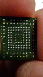
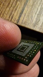
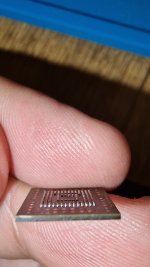
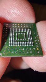
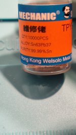
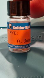
Inspired by @Takezo-San recent achievement and being bored while waiting for my new Oled to arrive I thought I'd give it a try a put the Ball in Reball a.k.a trying to do a reball without stencil or paste just by arranging the solder balls manually.
And what do you know, turned out much better than I expected.
This was an emmc 153 pulled from an old phone so there is still some way to go until I decide to do this on Switch but I’m getting there
Edit:
The process: spread a thin layer of flux on emmc (with finger); arrange the balls; heat them on 300°C lowest air flow until they are attached to surface; add more flux on top of them and reheat with 300°C medium airflow until nice and shiny; clean the flux as if your life depended on it.
Attachments
Last edited by QuiTim,
Ok bad news, tried the yellow dat0 adapter instead of the OAT0 I was using before and I still get the failed to init emmc error. Reading is once again 0.7v. Anything else that I could be doing wrong?
Amazing stuff. Did the old phone work with reball reintall and how did you manage to place those fiddly balls on top of the pads. I tried to use solder balls but there was no divet in the chip pads for them to settle in. Hence I opted to stick with the paste. But yes! We inspire and motivate each other. I just hope we can inspire others to do the same and discard the thought of dat0 adaptors that are hit or miss. Great work!Inspired by @Takezo-San recent achievement and being bored while waiting for my new Oled to arrive I thought I'd give it a try a put the Ball in Reball a.k.a trying to do a reball without stencil or paste just by arranging the solder balls manually.
And what do you know, turned out much better than I expected.
This was an emmc 153 pulled from an old phone so there is still some way to go until I decide to do this on Switch but I’m getting there
Edit:
The process: spread a thin layer of flux on emmc (with finger); arrange the balls; heat them on 300°C lowest air flow until they are attached to surface; add more flux on top of them and reheat with 300°C medium airflow until nice and shiny; clean the flux as your life depended on it.
Edit - Just saw the video. So you slide the balls into place. Got it. But how did you stop them from flying away with your hot air station? Low air flow/high heat?
Last edited by Takezo-San,
Amazing stuff. Did the old phone work with reball reintall and how did you manage to place those fiddly balls on top of the pads. I tried to use solder balls but there was no divet in the chip pads for them to settle in. Hence I opted to stick with the paste. But yes! We inspire and motivate each other. I just hope we can inspire others to do the same and discard the thought of dat0 adaptors that are hit or miss. Great work!
Edit - Just saw the video. So you slide the balls into place. Got it. But how did you stop them from flying away with your hot air station? Low air flow/high heat?
Just low are flow and heat till they beginn to melt then u can use more airflow.
Balls are cool but also a pain in the Ass that's why I prefer the past works faster and easier
The phone was dead long ago so no way to know.Amazing stuff. Did the old phone work with reball reintall and how did you manage to place those fiddly balls on top of the pads. I tried to use solder balls but there was no divet in the chip pads for them to settle in. Hence I opted to stick with the paste. But yes! We inspire and motivate each other. I just hope we can inspire others to do the same and discard the thought of dat0 adaptors that are hit or miss. Great work!
Edit - Just saw the video. So you slide the balls into place. Got it. But how did you stop them from flying away with your hot air station? Low air flow/high heat?
As for the process, I edited my original post with more info but just briefly, once you put some flux on the emmc the balls are easy to arange, once that's done 300° lowest airflow until the balls stick to emmc, afterwards add more flux all over the emmc and heat again 300° medium airflow until everything is set nicely. 30min total.
The balls have a melting point of around 190° so that makes everything easier.
My only concern with the whole reball process is that I have no reall feel of the amount of heat emmc can take without sustaining damage since I don't have a "real" rework station, the actual temperature from my heatgun can vary :/
This is what i'm currently using:
https://a.aliexpress.com/_mqrLI16
Would this modchip belong to this thread?

If so, I'll ask mods to move one post of mine to here...

If so, I'll ask mods to move one post of mine to here...
I guess this has been answered before but have a 2 switches boards one had-cpu-01 and had-cpu-10:
-worked fine for a few days able to boot into cfw and ofw no problems, rp2040 zero board(2.67fw) from waveshare 94ohm resistor on data 47ohm cmd resistor on CLK. Used hwfly CPU flex
-started with 0dat issues, eventually resulted in BSOD - no sd card ok hekate black screen (i can see separate thread on picofly aio read over 40 pages but have not found any conclusive problem)
-later found that due to the fact that the CPU heatsink is close to cmd it got shorted. which has been resolved but did not fixed the issue.
-Switch takes 0.08a steady draw on idle, apu capacitors shorted capacitors near ram shorted capacitors near 77812 shorted.
What i have noticed that once i shut down from the CFW (power>shut) the console shut and the picofly go through another sequence (i think it is blue to green on shutdown)? I think that first BSOD resulted once I have disconnected the SD card adapter before the sequence occurred then I was getting the BSOD after that.
Now the second board does go into NO SD - hekate result in black screen booting to ofw result in pico flashing dat0 fault with black screen
I have scraped the first switch for test purposes and noticed that the right row (looking where the flex is installed) all capacitors are 100ohm where working board has 2.5k ohm (even after all capacitors has been removed around apu and apu desolered from the board
Any help would be much appreciated - IMHO its apu short and its doner board now but would love to hear that i am wrong and it can be somehow saved
Last edited by Moromoromoro,
Similar threads
- Replies
- 4
- Views
- 2K
- Replies
- 2
- Views
- 630
- Replies
- 42
- Views
- 7K
Site & Scene News
New Hot Discussed
-
-
28K views
New static recompiler tool N64Recomp aims to seamlessly modernize N64 games
As each year passes, retro games become harder and harder to play, as the physical media begins to fall apart and becomes more difficult and expensive to obtain. The... -
25K views
Nintendo officially confirms Switch successor console, announces Nintendo Direct for next month
While rumors had been floating about rampantly as to the future plans of Nintendo, the President of the company, Shuntaro Furukawa, made a brief statement confirming... -
23K views
TheFloW releases new PPPwn kernel exploit for PS4, works on firmware 11.00
TheFlow has done it again--a new kernel exploit has been released for PlayStation 4 consoles. This latest exploit is called PPPwn, and works on PlayStation 4 systems... -
22K views
Nintendo takes down Gmod content from Steam's Workshop
Nintendo might just as well be a law firm more than a videogame company at this point in time, since they have yet again issued their now almost trademarked usual...by ShadowOne333 129 -
21K views
Name the Switch successor: what should Nintendo call its new console?
Nintendo has officially announced that a successor to the beloved Switch console is on the horizon. As we eagerly anticipate what innovations this new device will... -
17K views
A prototype of the original "The Legend of Zelda" for NES has been found and preserved
Another video game prototype has been found and preserved, and this time, it's none other than the game that spawned an entire franchise beloved by many, the very...by ShadowOne333 32 -
14K views
DOOM has been ported to the retro game console in Persona 5 Royal
DOOM is well-known for being ported to basically every device with some kind of input, and that list now includes the old retro game console in Persona 5 Royal... -
12K views
AYANEO officially launches the Pocket S, its next-generation Android gaming handheld
Earlier this year, AYANEO revealed details of its next Android-based gaming handheld, the AYANEO Pocket S. However, the actual launch of the device was unknown; that... -
11K views
Delta emulator for iOS will support iPad devices in its next update
With just a couple weeks after its initial release in the App Store, the Delta emulator for iOS was received with great success, after Apple loosened up its rules in...by ShadowOne333 35 -
11K views
Anbernic reveals the RG35XXSP, a GBA SP-inspired retro handheld
Retro handheld manufacturer Anbernic has revealed its first clamshell device: the Anbernic RG35XXSP. As the suffix indicates, this handheld's design is inspired by...
-
-
-
293 replies
Name the Switch successor: what should Nintendo call its new console?
Nintendo has officially announced that a successor to the beloved Switch console is on the horizon. As we eagerly anticipate what innovations this new device will...by Costello -
232 replies
Nintendo officially confirms Switch successor console, announces Nintendo Direct for next month
While rumors had been floating about rampantly as to the future plans of Nintendo, the President of the company, Shuntaro Furukawa, made a brief statement confirming...by Chary -
133 replies
New static recompiler tool N64Recomp aims to seamlessly modernize N64 games
As each year passes, retro games become harder and harder to play, as the physical media begins to fall apart and becomes more difficult and expensive to obtain. The...by Chary -
129 replies
Nintendo takes down Gmod content from Steam's Workshop
Nintendo might just as well be a law firm more than a videogame company at this point in time, since they have yet again issued their now almost trademarked usual...by ShadowOne333 -
95 replies
Ubisoft reveals 'Assassin's Creed Shadows' which is set to launch later this year
Ubisoft has today officially revealed the next installment in the Assassin's Creed franchise: Assassin's Creed Shadows. This entry is set in late Sengoku-era Japan...by Prans -
87 replies
The Kingdom Hearts games are coming to Steam
After a little more than three years of exclusivity with the Epic Games Store, Square Enix has decided to bring their beloved Kingdom Hearts franchise to Steam. The...by Chary -
80 replies
TheFloW releases new PPPwn kernel exploit for PS4, works on firmware 11.00
TheFlow has done it again--a new kernel exploit has been released for PlayStation 4 consoles. This latest exploit is called PPPwn, and works on PlayStation 4 systems...by Chary -
78 replies
"Nintendo World Championships: NES Edition", a new NES Remix-like game, launching July 18th
After rumour got out about an upcoming NES Edition release for the famed Nintendo World Championships, Nintendo has officially unveiled the new game, titled "Nintendo...by ShadowOne333 -
71 replies
DOOM has been ported to the retro game console in Persona 5 Royal
DOOM is well-known for being ported to basically every device with some kind of input, and that list now includes the old retro game console in Persona 5 Royal...by relauby -
65 replies
Microsoft is closing down several gaming studios, including Tango Gameworks and Arkane Austin
The number of layoffs and cuts in the videogame industry sadly continue to grow, with the latest huge layoffs coming from Microsoft, due to what MIcrosoft calls a...by ShadowOne333
-
Popular threads in this forum
General chit-chat
- No one is chatting at the moment.
-
-
-
-
-
-
-
-
-
-
-
-
-
-
-
-
-
-
-
 @
SenorED:
jkkkkkkkkkkkkkkkkkkkkkkkkkkkkkkkkkkk https://www.youtube.com/watch?v=2ryWgzW4RLI&ab_channel=MarioBendor'sComentario
kkkkkkkkkkkkkkkkkkkkkkkkkkkkkkkkk -
-
-
-
-
-


