Hacking Hardware Picofly - a HWFLY switch modchip

johndoenut

Member
Newcomer
Joined
Jun 16, 2023
Messages
8
Trophies
0
Age
27
XP
42
Country
United States
You got problem here.
cmd pad is ripped out.
Try to jumper that 2 point.
You need to revive the switch first, then decide whether you want to continue the mod.
View attachment 378238
Nice graphic. Do think I’ll be lucky enough to revive it? I’ve read people scratch the board to expose more copper but I’m not sure if the same can be done with this trace. As for trying the the mod again, probably not soon because of my subpar materials and tools, probably my skills too 😂. I think the wire I chose was too thick and contributed to the pad ripping off, as well as some old bad solder I used.
 
  • Like
Reactions: cgtchy0412

cgtchy0412

Well-Known Member
Member
Joined
Apr 26, 2023
Messages
287
Trophies
0
Age
41
XP
438
Country
Indonesia
Nice graphic. Do think I’ll be lucky enough to revive it? I’ve read people scratch the board to expose more copper but I’m not sure if the same can be done with this trace. As for trying the the mod again, probably not soon because of my subpar materials and tools, probably my skills too 😂. I think the wire I chose was too thick and contributed to the pad ripping off, as well as some old bad solder I used.
Yes, if you have like broken rumble motor (from ds1,ds2,ds3 controller),, you can extract some fine wires from that.. use that to jumper the point. It can be done with generic soldering tool, you just need steady hand and good lighting.
That silver dot in your pic is like screaming.. solder me solder me .... hahahha. :rofl2:
 
  • Like
Reactions: johndoenut

floxcap

Well-Known Member
Newcomer
Joined
May 21, 2023
Messages
69
Trophies
0
XP
281
Country
Australia
Nice graphic. Do think I’ll be lucky enough to revive it? I’ve read people scratch the board to expose more copper but I’m not sure if the same can be done with this trace. As for trying the the mod again, probably not soon because of my subpar materials and tools, probably my skills too 😂. I think the wire I chose was too thick and contributed to the pad ripping off, as well as some old bad solder I used.
It can be done - I had that exact problem and managed to fix it - but you have to be super careful - there's GND copper in the layers - so you have to be sure to have enough clearance & no shorts.
 

deeps

Well-Known Member
Member
Joined
Jul 3, 2007
Messages
454
Trophies
1
XP
1,278
Country
trying to find useful posts in this thread be like
 

Attachments

  • pepperidge.png
    pepperidge.png
    282.1 KB · Views: 20

CodyRoseman

Active Member
Newcomer
Joined
Apr 27, 2023
Messages
41
Trophies
0
Age
27
XP
101
Country
Australia
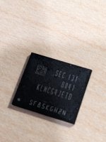
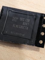
Hey, I don't know if I should post this here, but it seems appropriate. Does anyone want to buy a KLMEG8UCTA-B041 256GB eMMC and a KLMCG4JETD-B041 64GB eMMC, one is an original eMMC from an OLED and the 256GB was for an upgrade that I no longer can be bothered doing.

Name your price

PXL_20230616_092408670.jpg
 

Attachments

  • PXL_20230616_092528408.jpg
    PXL_20230616_092528408.jpg
    1.6 MB · Views: 18
  • PXL_20230616_092530227.jpg
    PXL_20230616_092530227.jpg
    1.6 MB · Views: 17

jeka1981

Active Member
Newcomer
Joined
Mar 13, 2018
Messages
43
Trophies
0
Age
42
XP
842
Country
Moldova
My story : i installed picofly on Switch Oled adn everything was fine/ Then i went for a cup of coffee. When i came back and pushed power button - nothing. Made hard reset and i saw a error for a few seconds - didn't managed to take a picture. It restarted itself an after that it get stucked on LOGO. I did unbrick level 1 and nothing. After i did unbrick level 2 it resurrected.
 

giovany86

Well-Known Member
Member
Joined
Oct 31, 2016
Messages
117
Trophies
0
XP
1,471
Country
France
Hello. Newbie here. I did a pico installation on a lite switch (using the v2 cable). It work fine and would boot into hekate. The issues started a couple hours later when running a atmosphere fusee payload. It would freeze inside the cfw, then when launching atmosphere and started giving me a 2002-3537 error code. When I removed the sd, it would show the no sd screen, and would show black screen with flashing yellow lights with the sd installed. Finally it would do nothing but the blue then yellow flashing =** whether it had an sd inserted or not. Decided to desolder all wires and flex cable to check if it would launch into ofw but no luck. Just a black screen no signs of life. One of the two Cmd pads was ripped off during installation but it worked earlier like that ( to my knowledge, unless I had bridged it with solder without noticing). I left it charging in hopes of a miracle but no signs of life, until later when the home button led turned on. Still won’t turn on with hard reset or charger. Can the broken Cmd pad cause this issue or was it likely something else? Here are some pictures of the pads. ( sorry, I don’t own a microscope. These were taken with an iPhone)
Assuming you have the tools to do so, you'll need to remove the emmc chip and run a jumper wire from emmc pad to the still standing point next to the one you damaged.

And by looking at the board scan, you clearly don't want to expose more copper as it's a ground plane and you'll most likely render the board unfixable (see second pic attached).

1686912648098.png


1686912766467.png
 
  • Like
Reactions: Danook28 and Dee87

hippy dave

BBMB
Member
Joined
Apr 30, 2012
Messages
9,946
Trophies
2
XP
30,344
Country
United Kingdom
My story : i installed picofly on Switch Oled adn everything was fine/ Then i went for a cup of coffee. When i came back and pushed power button - nothing. Made hard reset and i saw a error for a few seconds - didn't managed to take a picture. It restarted itself an after that it get stucked on LOGO. I did unbrick level 1 and nothing. After i did unbrick level 2 it resurrected.
This is why coffee is bad.
 
  • Like
  • Haha
Reactions: jeka1981 and QuiTim

MertX2

Member
Newcomer
Joined
Oct 16, 2022
Messages
17
Trophies
0
Age
35
XP
218
Country
Germany
Hey so I installed a one cap picofly mod in a switch because I think I broke the left capacitors pad (should I take the cap off?) so I only soldered to the right capacitor. Currently the switch does not boot and neither does the rp2040(no led at all). What could I test to diagnose it?
 

Dee87

Well-Known Member
Member
Joined
Mar 19, 2023
Messages
1,139
Trophies
1
XP
1,589
Country
Germany
Hey so I installed a one cap picofly mod in a switch because I think I broke the left capacitors pad (should I take the cap off?) so I only soldered to the right capacitor. Currently the switch does not boot and neither does the rp2040(no led at all). What could I test to diagnose it?
Pictures tell more then thousend words Xd

otherwise its hard to say what u coulda done wrong
 

abal1000x

Well-Known Member
Member
Joined
Jun 5, 2022
Messages
1,070
Trophies
0
XP
1,406
Country
Gaza Strip
Hey so I installed a one cap picofly mod in a switch because I think I broke the left capacitors pad (should I take the cap off?) so I only soldered to the right capacitor. Currently the switch does not boot and neither does the rp2040(no led at all). What could I test to diagnose it?
Check the resistance of the right cap (the good one) pins. Make sure its not shorted.
 
  • Like
Reactions: Dee87

hjohn

Member
Newcomer
Joined
Jun 13, 2023
Messages
9
Trophies
0
Age
31
XP
34
Country
Hungary
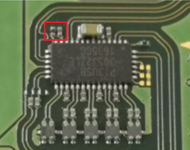
Sorry for kinda off topic, but this forum is really active. Can you help me identify this 2 component near PI3USB chip? I lost them and now I do not have image while docked.
One of them is a cap and the other looks like a resistor on this photo. Do any of you know the values, or could measure it for me? I need it for a v2 switch, but probably all the same.
Post automatically merged:

Hey so I installed a one cap picofly mod in a switch because I think I broke the left capacitors pad (should I take the cap off?) so I only soldered to the right capacitor. Currently the switch does not boot and neither does the rp2040(no led at all). What could I test to diagnose it?
Get a new 2040 It's less than 3$ and you fixed 1 problem. Check caps on CPU if shorted (with resistance and diode mode not continuity, the values so low, continuity will beep). Also check the board for other errors, maybe something else causing the issue you did before or after the cpu.
 

Attachments

  • PI3USB missing.png
    PI3USB missing.png
    452.4 KB · Views: 19
Last edited by hjohn,
  • Like
Reactions: Danook28

MertX2

Member
Newcomer
Joined
Oct 16, 2022
Messages
17
Trophies
0
Age
35
XP
218
Country
Germany
Thanks for the advice!
Resistance on the right cap was 20.3ohms after installation.
Is it really fine to blast the APU with hot air? 350C should be fine right?
And pictures are coming shortly as I currently dont have the switch with me.
 

Dee87

Well-Known Member
Member
Joined
Mar 19, 2023
Messages
1,139
Trophies
1
XP
1,589
Country
Germany
Thanks for the advice!
Resistance on the right cap was 20.3ohms after installation.
Is it really fine to blast the APU with hot air? 350C should be fine right?
And pictures are coming shortly as I currently dont have the switch with me.
Yeah u can blast it with hot air no problem just don't do it to long, add some low temp solder to the cap then it won't take as much heat, u can take a cap from the pico its not needed there, check the picofly install guide pretty sure they are showed which ones they are :)
 

hjohn

Member
Newcomer
Joined
Jun 13, 2023
Messages
9
Trophies
0
Age
31
XP
34
Country
Hungary
Thanks for the advice!
Resistance on the right cap was 20.3ohms after installation.
Is it really fine to blast the APU with hot air? 350C should be fine right?
And pictures are coming shortly as I currently dont have the switch with me.
Fine to use hot air (caps are so small, they heating up way earlier than SoC) use small nozzle. Other method: you can use wick to clear pads and solder the caps one side at a time with iron.
 
  • Like
Reactions: QuiTim

FreeLander

Well-Known Member
Member
Joined
Apr 6, 2023
Messages
350
Trophies
0
Age
35
XP
467
Country
United States
Hello. I removed the buttons and USB before flashing, duh.

I resoldered the USB points but I always get multiple flashes (like being plugged in without boot button pushed).

Could not boot it into flashing mode. How can I simulate the boot button being pushed with wires? Thanks.

IMG_7577.JPG
 

Site & Scene News

Popular threads in this forum

General chit-chat
Help Users
    BigOnYa @ BigOnYa: I played the intro to far cry 5, that is like some crazy Jim Jones cult shit. Still its petty...