Those resistors are holding on for dear life. Check diode readings on all points and report back with values
Sent from my iPhone using Tapatalk
Rst. 1. 176v
3v3. 0.852v
GND.ground.
Dat// 0.439v
Cmd//0.614v
CLK//0.775v
Cpu. 0.373 v
Those resistors are holding on for dear life. Check diode readings on all points and report back with values
Sent from my iPhone using Tapatalk
Confirmed (same as in photo)Hi guys,
Installing the picofly I burned the CMD resistor in my OLED switch.
I read in other post that the resistor that is sitting on the CMD point is 4k7 ohm and the one beside that is 47k ohm, both 0201 size.
Can you confirm the value and the size?
I want to confirm before order them.
Thanks and regards
You MUST solder flex anchor points/legs. Those are the Source (S terminal) of the flex. It will provide much better connection then soldering to capacitors only and it will make sure you don't rip off the flex and capacitors by mistakeIm sorry it is first install. And any thing wrong plz told me what I do wrong. Thanks. Im still not soldring Flex legs i was thinking on my console it is new.
Confirmed
Post automatically merged:
You MUST solder flex anchor points/legs. Those are the Source (S terminal) of the flex. It will provide much better connection then soldering to capacitors only
No surprise there. I guess you took your time to do the reading, all necessary preparations and followed the guide so this is what you getMy work for oled with 2.73
Instant boot in 1s, so surprise.
Thanks allll
After you solder anchor?It start boot to this pico logo no sd. Now it is boot ofw.
The Boot no sd card befor soldring legs. Now i well soldring legs brother.No surprise there. I guess you took your time to do the reading all necessary preparations and followed the guide so this is what you get
Post automatically merged:
After you solder anchor?
Make sure the SP1&SP2 are still connected
Is everything working now?The Boot no sd card befor soldring legs. Now i well soldring legs brother.
- shorten wires.Im sorry it is first install. And any thing wrong plz told me what I do wrong. Thanks. Im still not soldring Flex legs i was thinking on my console it is new.
- shorten wires.
- cannot see your sp1-sp2 solder joints!
- good idea to clean off thermal paste completely while installing the mod
If you expect people to help you with partial pictures of your mod then expect partial advice. Though in conclusion, slow timings probably length of wire and/or flex cable. If you are skilled enough, mosfets will make glitch faster (most likely) however, if you haven't done mosfet build before....practise.
Hope it helps
Hi guys.double post, i wrote here.
Good morning.
I update the situation of this installation.
I double-checked all soldering (including the mosfet, gate, source, drain ones).
They are all very stable, and well insulated by UV mask + 2 layers of kapton, I am very considerate as in the event of an impact these points could come into contact with the APU frame/shield.
I wondered if the RP2040 might have had some problems/damages, because it ran for several hours, passed various installs and backups.
So I replaced it and installed a new RP2040 with FW 2.74 using the already existing cables, so no changes in the installation (I didn't add sda/scl wires).
Now it works again and I could use but microsd that I had already prepared.
I therefore take advantage of your experience to try 3 questions.
1) What could have happened? Could the rp2040 have lost/damaged the fw (it was on 2.73)? I remind you that after a blue/cyan flash, the LED turned yellow and flashed several times (see video in the previous post)
2) I've run hekate, emummc several times and everything seems to work fine now, but as I have to ship this console, I'm afraid it might happen again.
3) Could FW 2.73 have caused this problem?
I'm going to go all the way, so I'll reinstall the "usb c" port, voltage regulator and boot key to flash the fw 2.74 and use this rp2040 which caused problems on a console from a customer in my area (I'll do it myself today ).
Waiting for your answers, I will update you on the RP2040 in question today.
I soldering legs it boot to ofw. After tearn it off. Little time it blinking blue then yellow. But nothing happend. I think it is firmware must update to 3.74Is everything working now?
Honestly, its just to risky to leave it. This mod requires the installer to not take any chances. NONE! NONE I TELLS YA!!!@Dee87 calls me Thermal Skywalker cause I hate thermal paste so much. Tied with my hatred of glitter for the same reason:
'it gets everywhere...'
If it's a mod, I clean it all immediately. If it's a repair, I constantly clean only what I need to work on at that time, until I prove that it's fixable.
I ABSOLUTELY LOVE that you advised cleaning it.
*Does his best impression of a noob*I soldering legs it boot to ofw. After tearn it off. Little time it blinking blue then yellow. But nothing happend. I think it is firmware must update to 3.74
I forgot the photos and videos.Hi guys.
As I told you, I overwrote the FW 2.74 on the RP2040 that had given me problems on another console and I installed it on another console.
I start by saying that the boot is instantaneous (while on the previous console it took longer) and for now it works regularly (started and shut down several times).
I remind you that the previous console is now working with another RP2040 with fw 2.74.
What may have happened?
Do you have an explanation?
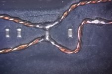
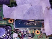
By the way, I patented the fish-shaped welds.
Mosfet-fish.
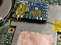
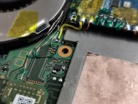
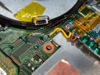
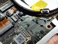
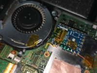
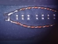
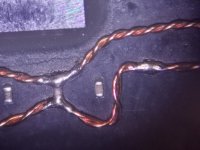
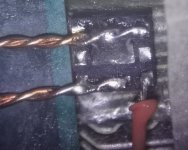
- shorten wires.
- cannot see your sp1-sp2 solder joints!
- good idea to clean off thermal paste completely while installing the mod
If you expect people to help you with partial pictures of your mod then expect partial advice. Though in conclusion, slow timings probably length of wire and/or flex cable. If you are skilled enough, mosfets will make glitch faster (most likely) however, if you haven't done mosfet build before....practise.
Hope it helps
especially that bottom one, looks super lean on solder and should have a solid connection to that cap endResolder these points, they look pretty flaky and they are the most vital ones to the glitch.
View attachment 374750
Starts and shut downs randomly.I forgot the photos and videos.
Picture pleeeeeeeeeeeeeeeeeeeeeeeeeeeeeease! And you say you disassembled the console, so how long ago was the working mod installed!?When I turn on the OLED, I get a pink screen immediately. I disassembled the console, found that the RST contact from rp2040 had fallen off. I put it back on, but the screen is still pink. As a result, all the contacts were soldered off and the screen is also pink. I killed the console or can I see something?
pink or purple?When I turn on the OLED, I get a pink screen immediately. I disassembled the console, found that the RST contact from rp2040 had fallen off. I put it back on, but the screen is still pink. As a result, all the contacts were soldered off and the screen is also pink. I killed the console or can I see something?
