Hacking Hardware Picofly - a HWFLY switch modchip

MicroRepairRX

Active Member
Newcomer
Joined
Jul 11, 2020
Messages
33
Trophies
0
Age
34
XP
176
Country
United States
Have a Mariko Switch V2 with SkHynix emmc. Installed the pico fly using two mosfests wired up and soldered to the points that aren't on the emmc.

Console looks like it's training blue then green but no picofly sd card screen, but boots to OFW.

Read the FAQ and it said put a 20-30k resistor on reset if the chip flashes green and resets,....I assume by reset they mean the OFW logo shows.

Add the 24K ohm resistor to the reset line and now it flashes blue then orange, then off.

Not sure what else to try. TIA
 
  • Like
Reactions: Danook28

NetYaroze

Member
Newcomer
Joined
Mar 30, 2023
Messages
22
Trophies
0
Age
36
XP
95
Country
Germany
Hello friends! I ordered these resistors from AliExpress, ( €1.05 | 50pcs 2512 5% SMD resistor 1W 10R 22R 24R 27R 30R 33R 36R 39R 43R 47R 51R 56R 62R 68R 22 24 27 30 33 36 39 43 47 51 56 100 ohm
https://a.aliexpress.com/_EvTG0LH ) I received them yesterday but they look really big compared to the ones I've seen here in several posts and comparse with rp2040 zero 😵‍💫. Can we suggest me the right resistors to buy? Right now I'm in Italy for work and I can order from Amazon italy for example. Thanks 😊
 
  • Like
Reactions: Danook28

vittorio

Well-Known Member
Member
Joined
May 12, 2014
Messages
243
Trophies
0
Age
26
XP
968
Country
Italy
Have a Mariko Switch V2 with SkHynix emmc. Installed the pico fly using two mosfests wired up and soldered to the points that aren't on the emmc.

Console looks like it's training blue then green but no picofly sd card screen, but boots to OFW.

Read the FAQ and it said put a 20-30k resistor on reset if the chip flashes green and resets,....I assume by reset they mean the OFW logo shows.

Add the 24K ohm resistor to the reset line and now it flashes blue then orange, then off.

Not sure what else to try. TIA
on newer firmwares no need to use resistor on rst anymore
 

deeps

Well-Known Member
Member
Joined
Jul 3, 2007
Messages
451
Trophies
1
XP
1,248
Country
Hello friends! I ordered these resistors from AliExpress, ( €1.05 | 50pcs 2512 5% SMD resistor 1W 10R 22R 24R 27R 30R 33R 36R 39R 43R 47R 51R 56R 62R 68R 22 24 27 30 33 36 39 43 47 51 56 100 ohm
https://a.aliexpress.com/_EvTG0LH ) I received them yesterday but they look really big compared to the ones I've seen here in several posts and comparse with rp2040 zero 😵‍💫. Can we suggest me the right resistors to buy? Right now I'm in Italy for work and I can order from Amazon italy for example. Thanks 😊
0805 is the size you want. example: https://www.aliexpress.com/item/100....order_list.order_list_main.63.372d1802Ho4eYm
 

Bradlin

Member
Newcomer
Joined
Apr 16, 2021
Messages
17
Trophies
0
XP
132
Country
France
Is the rp2040 source code available? I'm not talking about the PIO code (its source was already posted here), but the code of the CPU, i.e. the C or C++ code which sets up all the PIO programs and launches them.
 
  • Like
Reactions: Danook28

Adran_Marit

Walküre's Hacker
Member
Joined
Oct 3, 2015
Messages
3,781
Trophies
1
Location
42*South
XP
4,557
Country
Australia
Is the rp2040 source code available? I'm not talking about the PIO code (its source was already posted here), but the code of the CPU, i.e. the C or C++ code which sets up all the PIO programs and launches them.
it is not public
and it may never be. That is entirely upto the dev
 

Dandan0404

Well-Known Member
Member
Joined
Mar 25, 2023
Messages
131
Trophies
0
Age
23
XP
183
Country
Philippines
Hello, I hope everyone is doing well. After all the research, I'm finally going to be modding tomorrow.. I do have last final questions if any one can help

1.) Reformatted my switch , add my previous account with NSO Subscription. Will it reflect on sysnand? And can I still go online right safely?

2.) Due to unexpected situation, I have no official Joycons but a 3rd party dobe usbc connect controller. Are there any problems I may I encounter when Modding my switch??? (example "remove Joycons.." "attack Joycons to continue.." "simultaneously press ...."
 
  • Like
Reactions: Danook28

QuiTim

Well-Known Member
Member
Joined
Mar 30, 2023
Messages
756
Trophies
0
XP
1,159
Country
Albania
The wait finally came to an end. I installed the first one last night but it did take me longer then I expected (thanks to 3v3 point)

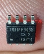
On my search to find some 47R resistors locally, I stumbled upon IRF8714 (SO-8) Mosfet and I thought why not, lets give it a shot (the alternative was to use V1 flex on Mariko since I’m still waiting on the order from Ali with mosfets, resistors, wires and everything)
I only used one IRF8714 (connected to both caps) and everything works ok (Inspired by @dave22 layout, thank you)
Being an SO-8, the mosfet is a bit large so I cut the shield between the APU and memory just to be sure, but the upside is that it’s really easy to solder (because of the size and terminal layout)
I also cut the outer shield just for the fun of it and I think it looks nice this way.
The only issue that I had was the original 3v3 point on the cap. I guess after couple of tries I lost my cool a ripped the upper pad of cap (as it can be seen in the photo), and then I went for the alternative point in emmc which I soldered in 5sec.

Used 2.65 firmware and there was no problem whatsoever, everything works as intended.

I would like to thank @rehius for the amazing work and all the time he put in this project, and also @lightninjay for compiling the information on the pdf, @Adran_Marit for AIO and all the tips.

I think the real win here was finding this community of amazing people who share a passion of doing incredible things and their willingness to help others and bring them along in this journey.

Cheers
20230420_231239.jpg
20230420_231634.jpg
20230421_015534.jpg
20230421_102913.jpg
20230421_102946.jpg
20230421_021418.jpg
20230420_120747.jpg
 

Pasx0

New Member
Newbie
Joined
Apr 21, 2023
Messages
2
Trophies
0
Age
26
XP
16
Country
Germany
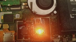
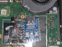
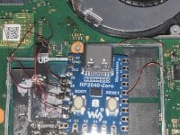
I'm currently trying to mod my V2 Switch using an rp2040 zero and the hwfly v2 cable, but its not working so far. I get a short blue flash followed by a short orange flash. The faq suggests that there is a problem with the dat0 connection to the emmc. I tried the solder/test points on the main switch pcb for clk, dat0 and cmd, as well as the points on the emmc. There shouldn't be any cold solder joints. I tested every connection using the test points on the main switch pcb. I've got the SKhynix emmc so this should also not be the problem. I've tried it with 47 ohm on dat0 and cmd, as well as with 94 ohm, both didn't work.

Some additional information:
- The switch doesn't boot when everything is connected
- The switch does boot to OFW when the rp2040 isn't connected to the 3V3
- I had to apply the rgb bridge on the rp2040

I'm out of ideas. It would be awesome if someone had some suggestions.
 

Attachments

  • 01_orangeFlash.jpg
    01_orangeFlash.jpg
    250.2 KB · Views: 51
  • 02_normal.jpg
    02_normal.jpg
    4.8 MB · Views: 72
  • 03_emmc.jpg
    03_emmc.jpg
    4.7 MB · Views: 55
  • Like
Reactions: Danook28

Hayato213

Newcomer
Member
Joined
Dec 26, 2015
Messages
20,014
Trophies
1
XP
21,091
Country
United States
I'm currently trying to mod my V2 Switch using an rp2040 zero and the hwfly v2 cable, but its not working so far. I get a short blue flash followed by a short orange flash. The faq suggests that there is a problem with the dat0 connection to the emmc. I tried the solder/test points on the main switch pcb for clk, dat0 and cmd, as well as the points on the emmc. There shouldn't be any cold solder joints. I tested every connection using the test points on the main switch pcb. I've got the SKhynix emmc so this should also not be the problem. I've tried it with 47 ohm on dat0 and cmd, as well as with 94 ohm, both didn't work.

Some additional information:
- The switch doesn't boot when everything is connected
- The switch does boot to OFW when the rp2040 isn't connected to the 3V3
- I had to apply the rgb bridge on the rp2040

I'm out of ideas. It would be awesome if someone had some suggestions.

Your soldering doesn't look very good.
 
  • Like
Reactions: Danook28

Pasx0

New Member
Newbie
Joined
Apr 21, 2023
Messages
2
Trophies
0
Age
26
XP
16
Country
Germany
yes I totally agree. I tried to fix some joints and it didn't really work out. But the connections used by the emmc all seem to work perfectly fine.
 
  • Like
Reactions: Danook28

Danook28

Well-Known Member
Member
Joined
Jul 17, 2018
Messages
497
Trophies
0
Age
34
XP
1,035
Country
Oman
The wait finally came to an end. I installed the first one last night but it did take me longer then I expected (thanks to 3v3 point)

On my search to find some 47R resistors locally, I stumbled upon IRF8714 (SO-8) Mosfet and I thought why not, lets give it a shot (the alternative was to use V1 flex on Mariko since I’m still waiting on the order from Ali with mosfets, resistors, wires and everything)
I only used one IRF8714 (connected to both caps) and everything works ok (Inspired by @dave22 layout, thank you)
Being an SO-8, the mosfet is a bit large so I cut the shield between the APU and memory just to be sure, but the upside is that it’s really easy to solder (because of the size and terminal layout)
I also cut the outer shield just for the fun of it and I think it looks nice this way.
The only issue that I had was the original 3v3 point on the cap. I guess after couple of tries I lost my cool a ripped the upper pad of cap (as it can be seen in the photo), and then I went for the alternative point in emmc which I soldered in 5sec.

Used 2.65 firmware and there was no problem whatsoever, everything works as intended.

I would like to thank @rehius for the amazing work and all the time he put in this project, and also @lightninjay for compiling the information on the pdf, @Adran_Marit for AIO and all the tips.

I think the real win here was finding this community of amazing people who share a passion of doing incredible things and their willingness to help others and bring them along in this journey.

CheersView attachment 366254View attachment 366256View attachment 366257View attachment 366258View attachment 366259View attachment 366260View attachment 366261
The mosfet fit under cpu case metal case?????
 

QuiTim

Well-Known Member
Member
Joined
Mar 30, 2023
Messages
756
Trophies
0
XP
1,159
Country
Albania
I'm currently trying to mod my V2 Switch using an rp2040 zero and the hwfly v2 cable, but its not working so far. I get a short blue flash followed by a short orange flash. The faq suggests that there is a problem with the dat0 connection to the emmc. I tried the solder/test points on the main switch pcb for clk, dat0 and cmd, as well as the points on the emmc. There shouldn't be any cold solder joints. I tested every connection using the test points on the main switch pcb. I've got the SKhynix emmc so this should also not be the problem. I've tried it with 47 ohm on dat0 and cmd, as well as with 94 ohm, both didn't work.

Some additional information:
- The switch doesn't boot when everything is connected
- The switch does boot to OFW when the rp2040 isn't connected to the 3V3
- I had to apply the rgb bridge on the rp2040

I'm out of ideas. It would be awesome if someone had some suggestions.
I see alot of flux residue. I would clean those first (if you have not done so yet). I had a similar problem on Oled, everything was ok, the flux was the issue.
Also check edhe continuity of those enamel wires, it can happen sometimes that they connect to the solder point but they are not conducting anything because the enamel coating did not melt while soldering, (especially on this red type that you are using since it has a higher temperature rating)
Post automatically merged:

The mosfet fit under cpu case metal case?????
Yes, almost perfect. I would say maybe by 0.1mm.
One thing that i should have done was maybe to cut half of the legs on mosfet because i think that solder getting under the leg gave it that extra 0.1 height.
 

Attachments

  • 20230420_120747.jpg
    20230420_120747.jpg
    401.5 KB · Views: 47
  • Like
Reactions: Danook28

B89BER

Member
Newcomer
Joined
Mar 30, 2023
Messages
5
Trophies
0
Age
35
XP
50
Country
Poland
Question. If I installed the RP2040 to one Switch and later want to transfer it to another, will it not cause problems?
 

Site & Scene News

Popular threads in this forum

General chit-chat
Help Users
  • No one is chatting at the moment.
    K3Nv2 @ K3Nv2: https://youtube.com/shorts/fRENPoVaZHk?si=0xgCyaSVzuc5GD5F