Hacking Hardware Picofly - a HWFLY switch modchip

abal1000x

Well-Known Member
Member
Joined
Jun 5, 2022
Messages
1,070
Trophies
0
XP
1,404
Country
Gaza Strip
Guys i've a question. today I get the cpu flat so I haven't installed the rp 2040 yet. But I had flashed the 2.5 firmware. If I want to update the firmware before installing it, just connect it to the pc with the boot button and load the new firmware version right?
fw2.5 doesn't have update mechanism.
The upate mechanism exist on on 2.61 up.

Editted:
Yes bootsel then drag the new firmware.
 
Last edited by abal1000x,

vittorio

Well-Known Member
Member
Joined
May 12, 2014
Messages
243
Trophies
1
Age
26
XP
1,003
Country
Italy
Guys i've a question. today I get the cpu flat so I haven't installed the rp 2040 yet. But I had flashed the 2.5 firmware. If I want to update the firmware before installing it, just connect it to the pc with the boot button and load the new firmware version right?
yes
 

rehius

Well-Known Member
Member
Joined
Feb 6, 2023
Messages
377
Trophies
1
Age
34
XP
1,790
Country
Canada
Thank you, i tried 2.65 with same result
i will try older versions too
could you please give more information regarding your console?
(eMMC hekate info, DRAM hekate info, revision?)

try the firmware with x2 "fast timeout" timings, the only thing I can think of
 

Attachments

  • fw_2.65_l.uf2.pdf
    240 KB · Views: 70

AntonIX

Active Member
Newcomer
Joined
Jan 14, 2023
Messages
34
Trophies
0
Age
24
Website
devpins.org
XP
217
Country
Russia
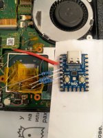
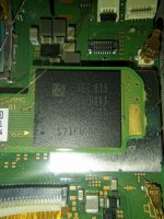
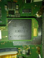
I am still getting pink and ofw. Tried with 20 ohm on rst. CMD, CLK and DAT0 tried with 100 ohm and without resistors(no ofw boot in this case), but the same result - pink (rgb mode is ok, red on flash). Tried different fw includes one for think wires and the last one which was a few posts ago. Where is my trouble? May be toshiba nand? (how i can check it without hecate)? My console is patched erista.
 

Attachments

  • picofly.jpg
    picofly.jpg
    173.6 KB · Views: 54
  • video_2023-04-14_14-18-50.mp4
    6.2 MB
  • photo_2023-04-14_14-25-19.jpg
    photo_2023-04-14_14-25-19.jpg
    279 KB · Views: 51
  • photo_2023-04-14_14-25-14.jpg
    photo_2023-04-14_14-25-14.jpg
    292.4 KB · Views: 47
  • Like
Reactions: impeeza

rehius

Well-Known Member
Member
Joined
Feb 6, 2023
Messages
377
Trophies
1
Age
34
XP
1,790
Country
Canada
I am still getting pink and ofw. Tried with 20 ohm on rst. CMD, CLK and DAT0 tried with 100 ohm and without resistors(no ofw boot in this case), but the same result - pink (rgb mode is ok, red on flash). Tried different fw includes one for think wires and the last one which was a few posts ago. Where is my trouble? May be toshiba nand? (how i can check it without hecate)? My console is patched erista.
show where the each wire goes, might be wrong connection
 
  • Love
Reactions: impeeza

TheBad

Well-Known Member
Newcomer
Joined
Apr 14, 2023
Messages
46
Trophies
0
Age
29
XP
279
Country
Turkey
I am struggling to find any compatible parts online in Turkey. I have find the parts below;

RP2040-One This is available in a local shop or,
Raspberry pi pico This one is also available. Which one to chose?

Also there are no recommended mosfet I can find so far. From my research I find mosfet below;
1681473133724.png
NTMFS4119N 30V 11A mosfet with small package. Are there any specifications for mosfet? RDS resistance, max capacitance, Current, Voltage capabilities etc.

I am planning to mod an OLED I have emmc adapter for it.
 
  • Like
Reactions: SkylerTakashi

KingMo5h

Active Member
Newcomer
Joined
Mar 12, 2023
Messages
26
Trophies
0
Age
33
XP
139
Country
Germany
Are these available for you BUK6D22-30EX ? These are pin compatible and have nearly the same characteristics but havent tested them yet.
 

AntonIX

Active Member
Newcomer
Joined
Jan 14, 2023
Messages
34
Trophies
0
Age
24
Website
devpins.org
XP
217
Country
Russia
show where the each wire goes, might be wrong connection
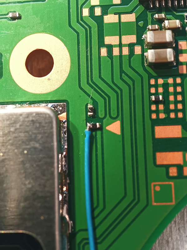
29 - DAT0, 28 - CMD, 17 - CLK. Seems like theese points soldered correctly. Anything else? I heard on 4pda thats it may work only with 47 ohm resisters in some cases. I am not sure about cpu, but light should be cyan.
 
Last edited by AntonIX,

Adran_Marit

Walküre's Hacker
Member
Joined
Oct 3, 2015
Messages
3,781
Trophies
1
Location
42*South
XP
4,569
Country
Australia
I am struggling to find any compatible parts online in Turkey. I have find the parts below;

RP2040-One This is available in a local shop or,
Raspberry pi pico This one is also available. Which one to chose?

Also there are no recommended mosfet I can find so far. From my research I find mosfet below;
View attachment 364885NTMFS4119N 30V 11A mosfet with small package. Are there any specifications for mosfet? RDS resistance, max capacitance, Current, Voltage capabilities etc.

I am planning to mod an OLED I have emmc adapter for it.

The rp2040-one fits better, try and get a flex cable from Ali if you can't find the recommended mosfet
Post automatically merged:

29 - DAT0, 28 - CMD, 17 - CLK. Seems like theese points soldered correctly. Anything else? I heard on 4pda thats it may work only with 47 ohm resisters in some cases.
can you upload photos of your work?
 

rehius

Well-Known Member
Member
Joined
Feb 6, 2023
Messages
377
Trophies
1
Age
34
XP
1,790
Country
Canada
29 - DAT0, 28 - CMD, 17 - CLK. Seems like theese points soldered correctly. Anything else? I heard on 4pda thats it may work only with 47 ohm resisters in some cases. I am not sure about cpu, but light should be cyan.
I mean show photos of the board, since it's hard to see where exactly those wires are soldered to. My diagrams assume soldering directly to the eMMC board, or, at least, to its header, I am unaware of other points. Just wanted to check
Post automatically merged:

@rehius were are the firmwares being uploaded?
Thx for all you work!
In the same message you just quoted
 
  • Like
Reactions: Dee87

Dandan0404

Well-Known Member
Member
Joined
Mar 25, 2023
Messages
131
Trophies
0
Age
23
XP
183
Country
Philippines
try the firmware with x2 "fast timeout" timings, the only thing I can think of
hello sir rehius, whats the difference between the normal uf and this new x2 timeout and the previous x1 timeout-ish? the other day. i will be using v3 oled flex cable soldering both resistors


Also guys, been researching for the past 2 months, somehow i already got the gist, but what are the particular specific issues or notes i should know about? like...

-RST point is very sensitive so make sure to clean it properly without flux leaving behind and covering some tape...

-Adding additional resistors if it doesnt work...

-20k resistor for RST if it does not work..

anymore?
 
Last edited by Dandan0404,

Site & Scene News

Popular threads in this forum

General chit-chat
Help Users
  • No one is chatting at the moment.
    K3Nv2 @ K3Nv2: https://youtube.com/shorts/wZgjSNb-o4c?si=ajt4Lgq_LTYcXxs2 +1