


So, I just built the Wiip based on the Gerb files the Wiip team released.
For those of you that know a little about electronics it's not something special.
But, I didn't put a DB25 connector, since it's quite big and makes the modchip bulky. Instead it's better to make the ??90S2313 removable, so you can put it in your programmer whenever it needs reprogramming.
So, let's begin with my awful quality pics.
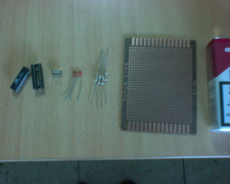
These are the parts we are going to use/ An AT90S2313 with its base, a crystall 4MHz, 2 22pF capacitors, 4x 220 ohm resistors and a board to solder them there.

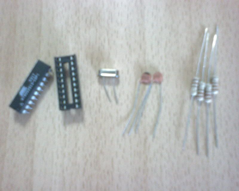
a close up

I also used a 1N4148 diode, a 100nF capacitor and a few pins
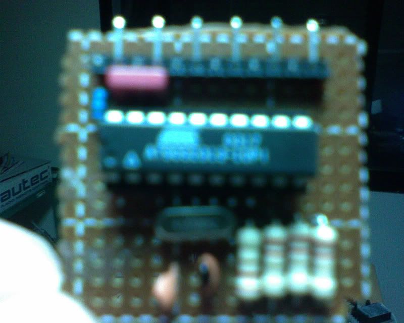
So, the Wiip completed is like this. I tried to make it as compact as possible

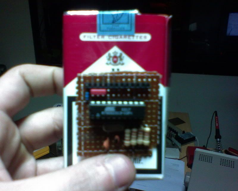
In this pic, I use a pac of cigarretes to compare the sizes

The modchip is about 5X5 cm
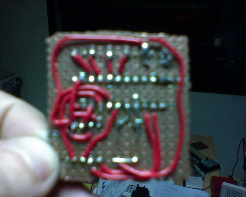
Here is the back view of the modchip. Nothing special.

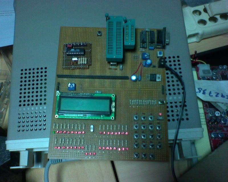
Here is the modchip with my development board

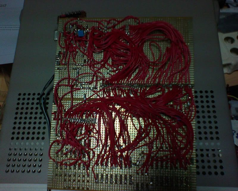
And the back view of the dev board

That's all. Now, if we only had the code.....
Edit:
Well, since I have my home-made dev board for avrs, I don't need a programmer, but I wanted to test if I could make the cheap SP12 programmer that is used for the Chiip.
See, AT90S2313 needs at least 4 Volts to operate (for -10PI 2313s) and from the LPT port you can have with the SP12 programmer 3.7V. Also, the SP12 programmer, in order to work with the AT90S2313, it needs a crystall 4MHz and 2 capacitors 22pF or 33pF.
So, I made it just to check it out and it workds flawlessly!!!
For the diagram, you need the first in this site: Programming a spider's brain
Also, from there you can download the program you'll use to upload the code to the microcontroller.
So here are the pics from the SP12 programmer for the AT90S2313:
I cut off the LPT connector from a printer cable which I don't need any more

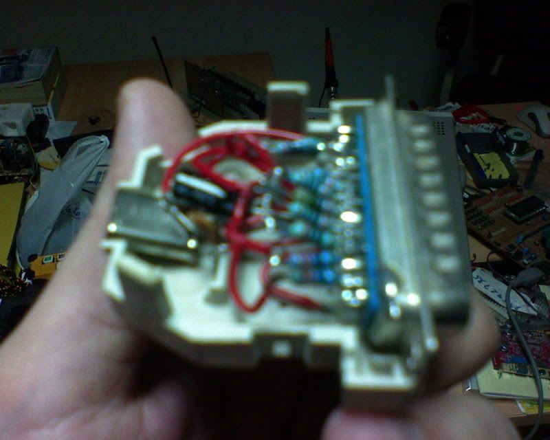
The components that you'll solder from behind are 9 resistors, 3 capacitors, one crystall and the base for the microcontroller.

It's a mess, but I did that because I wanted everything to fit inside the connector

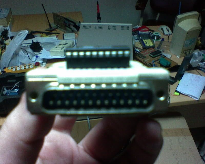
The base for the microcontroller is fitted above the plastic casing. I opened holes so that its pins can go through the casing.


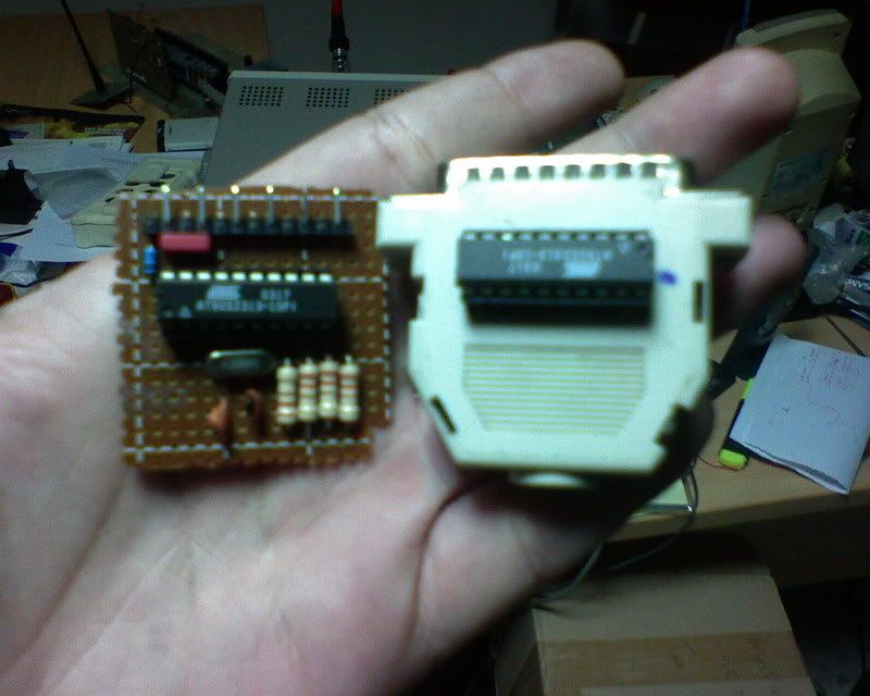
And here is the Wiip with the LPT programmer.

That's all
For those of you that know a little about electronics it's not something special.
But, I didn't put a DB25 connector, since it's quite big and makes the modchip bulky. Instead it's better to make the ??90S2313 removable, so you can put it in your programmer whenever it needs reprogramming.
So, let's begin with my awful quality pics.
These are the parts we are going to use/ An AT90S2313 with its base, a crystall 4MHz, 2 22pF capacitors, 4x 220 ohm resistors and a board to solder them there.
a close up
I also used a 1N4148 diode, a 100nF capacitor and a few pins
So, the Wiip completed is like this. I tried to make it as compact as possible
In this pic, I use a pac of cigarretes to compare the sizes
The modchip is about 5X5 cm
Here is the back view of the modchip. Nothing special.
Here is the modchip with my development board
And the back view of the dev board
That's all. Now, if we only had the code.....
Edit:
Well, since I have my home-made dev board for avrs, I don't need a programmer, but I wanted to test if I could make the cheap SP12 programmer that is used for the Chiip.
See, AT90S2313 needs at least 4 Volts to operate (for -10PI 2313s) and from the LPT port you can have with the SP12 programmer 3.7V. Also, the SP12 programmer, in order to work with the AT90S2313, it needs a crystall 4MHz and 2 capacitors 22pF or 33pF.
So, I made it just to check it out and it workds flawlessly!!!
For the diagram, you need the first in this site: Programming a spider's brain
Also, from there you can download the program you'll use to upload the code to the microcontroller.
So here are the pics from the SP12 programmer for the AT90S2313:
I cut off the LPT connector from a printer cable which I don't need any more

The components that you'll solder from behind are 9 resistors, 3 capacitors, one crystall and the base for the microcontroller.
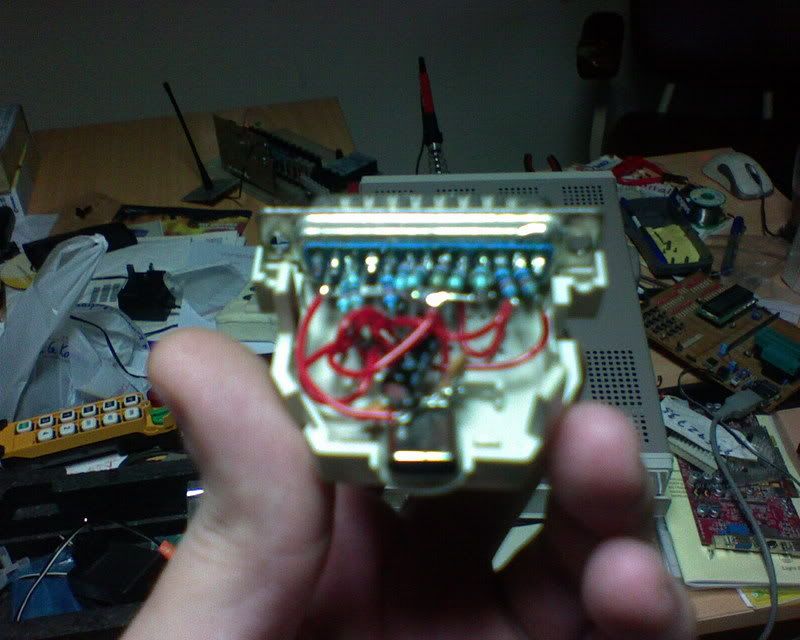
It's a mess, but I did that because I wanted everything to fit inside the connector
The base for the microcontroller is fitted above the plastic casing. I opened holes so that its pins can go through the casing.

And here is the Wiip with the LPT programmer.
That's all


