

Hardware Tutorial
Updated
New 3DS Screw and Hardware Measurements
Continuing in my series of screw measurement posts, we come to the New 3DS.

I've done screw measurement posts for several consoles (listed below), including every DS and 3DS console.
I did deeper dives into the DSi and DSi XL, pointing out any console-to-console differences.
Other posts can be found here:
- DS (Base)
- DS Lite
- DSi
- DSi XL
- 3DS (Base)
- 3DS XL
- 2DS
- New 2DS XL
- New 3DS
- New 3DS XL
- Switch Lite
Also, check out my DS and 3DS Screw Repository.
I have since updated this post with measurements from calipers. My original post will be buried within this spoiler tag.
I will use a custom chart I made as a reference to measure each screw with my calipers.
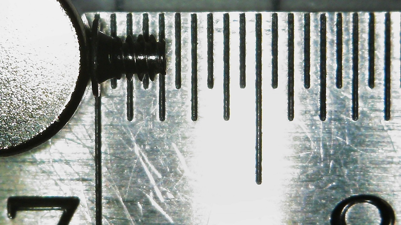
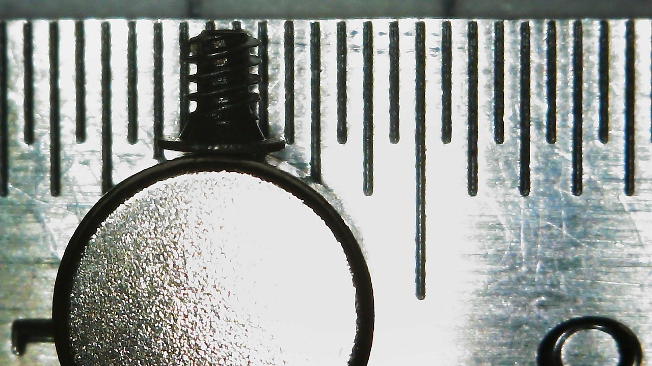
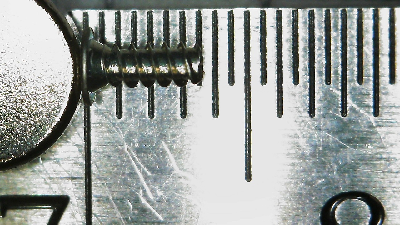
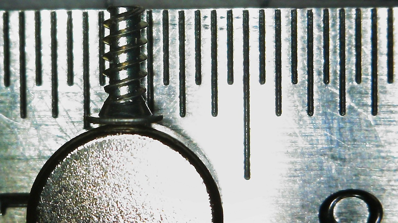
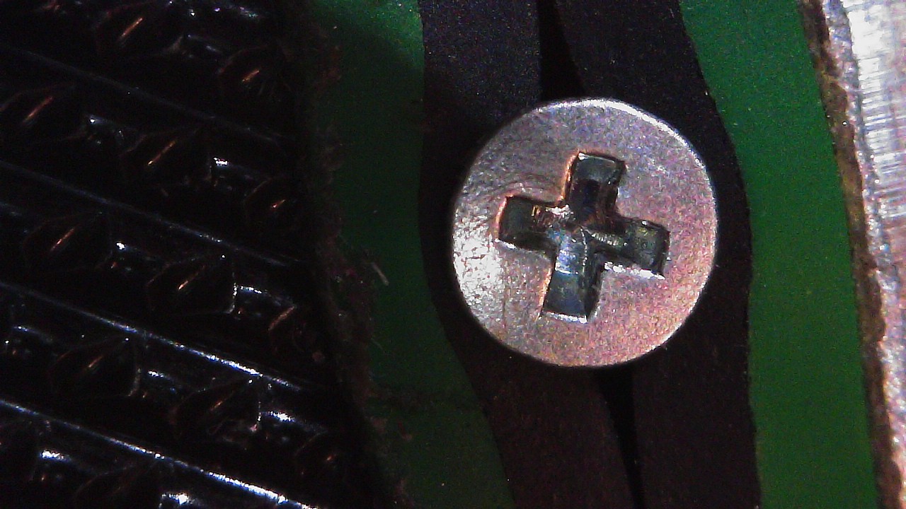
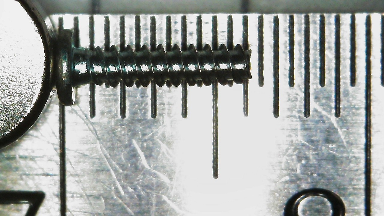
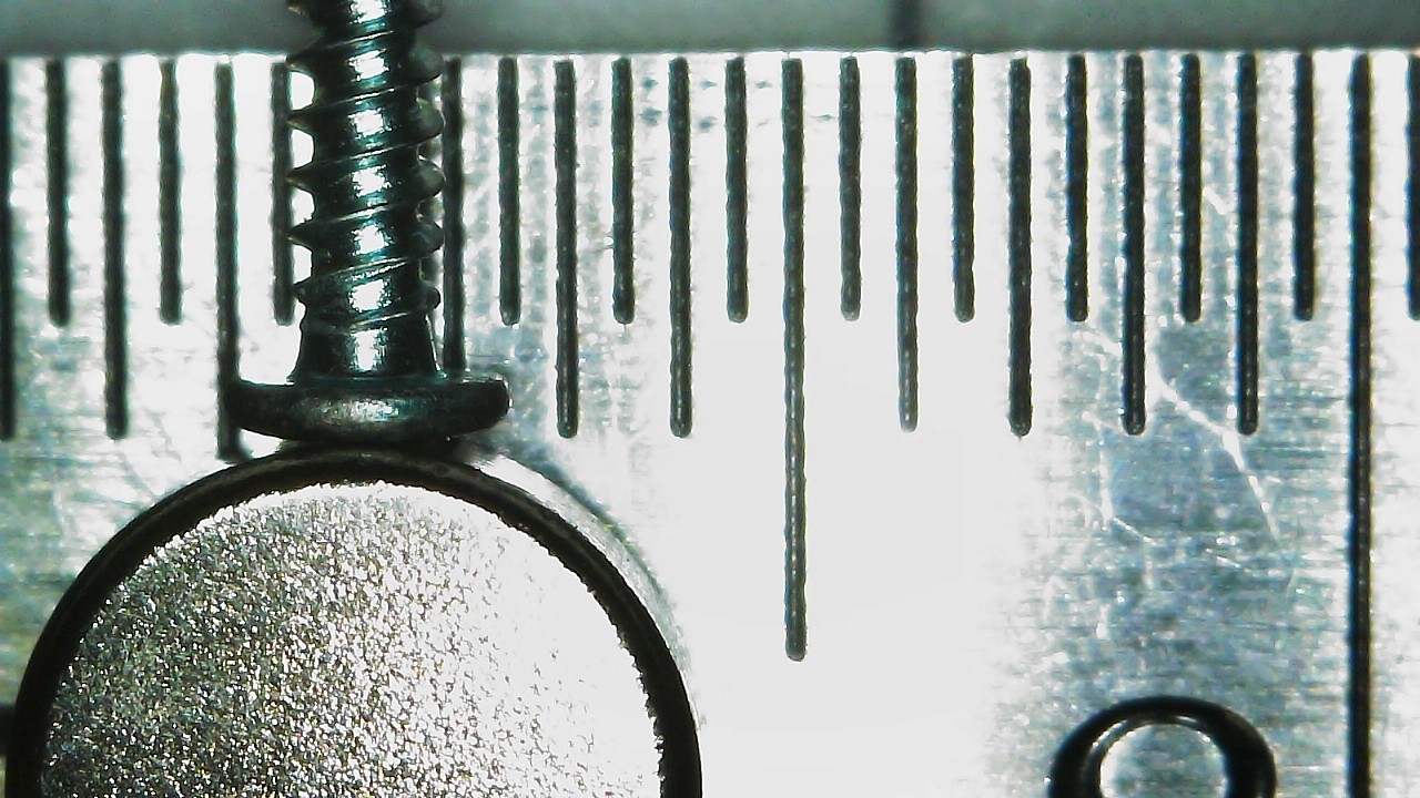
Measurements done with Calipers will only be done on one screw per category, and will be subject to some amount of inaccuracies due to the size of the screws and the tools I have. Measurements like Thread Pitch, Shank Length, Thread Length, and Recess Width are done by eyeballing it with my calipers and a microscope. Measurements like Thread Diameter and Screw Length will be far more accurate as I can physically clamp them in my calipers.
I'll add links to an IFixIt Guide to match my terms to pictures (i.e., Motherboard Screw would point to the Motherboard removal step of an IFixIt guide). If there is no guide, I won't be able to link.
The New 3DS guides on IFixIt are not complete as they do not include a step for removing the Top Screen. The drivers recommended in the guide match my experience, so I have nothing to say there.
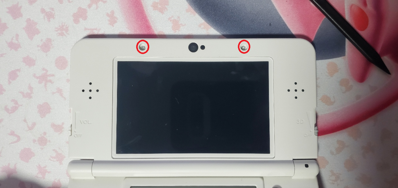
The only gripe I have with the guides is that the Motherboard removal step says there are three screws; however, there aren't. The screw circled on the top right, next to the top display and camera ribbon connector, is a through hole for one of the bottom shell screws. Screwing a motherboard screw there MAY be ok, but what it will do is plug the hole for the screw that belongs there.










I've done screw measurement posts for several consoles (listed below), including every DS and 3DS console.
I did deeper dives into the DSi and DSi XL, pointing out any console-to-console differences.
Other posts can be found here:
- DS (Base)
- DS Lite
- DSi
- DSi XL
- 3DS (Base)
- 3DS XL
- 2DS
- New 2DS XL
- New 3DS
- New 3DS XL
- Switch Lite
Also, check out my DS and 3DS Screw Repository.
I have since updated this post with measurements from calipers. My original post will be buried within this spoiler tag.
How I measured these screws.
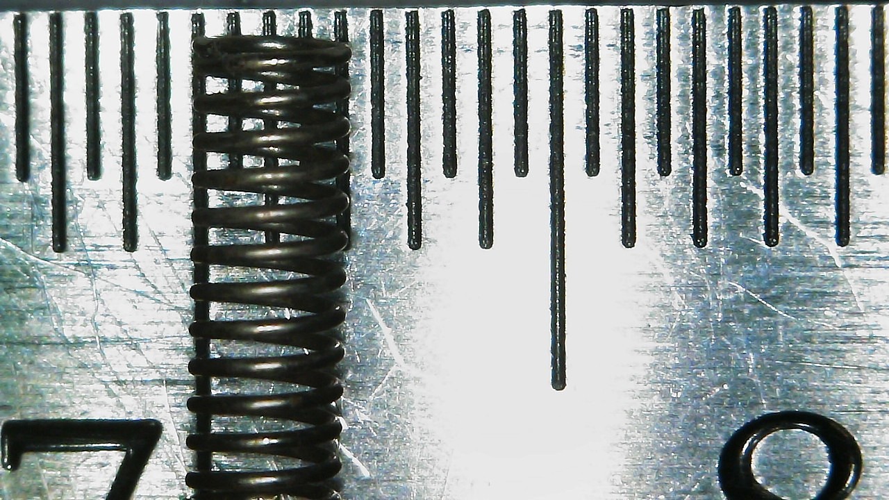
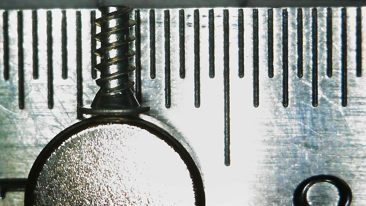
I measured the screws on a ruler with markings down to half-millimeter increments and a digital microscope. Measurements were taken similar to this image of measuring Thread Pitch below.

(Image Sourced from Albany County Fasteners' video, How to Measure Screws & Bolts - US & Metric Sizing | Fasteners 101)
Since I do not have specialty equipment to measure screws this small, I am forced to estimate; especially on the thread pitch itself. Take the measurements with the knowledge that it was done by someone who is a novice in screw measuring.
New 3DS
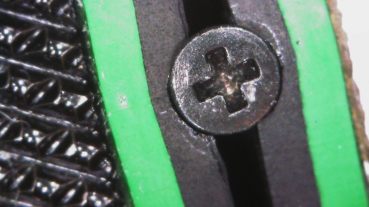
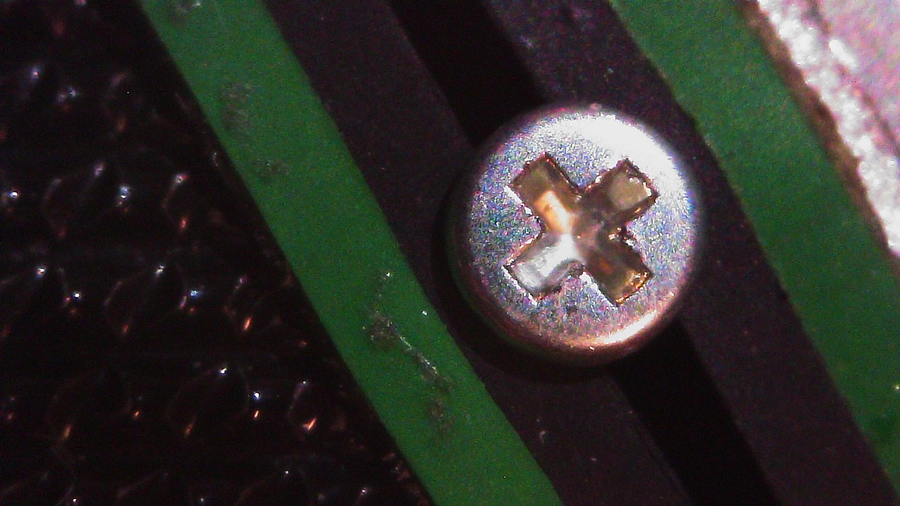
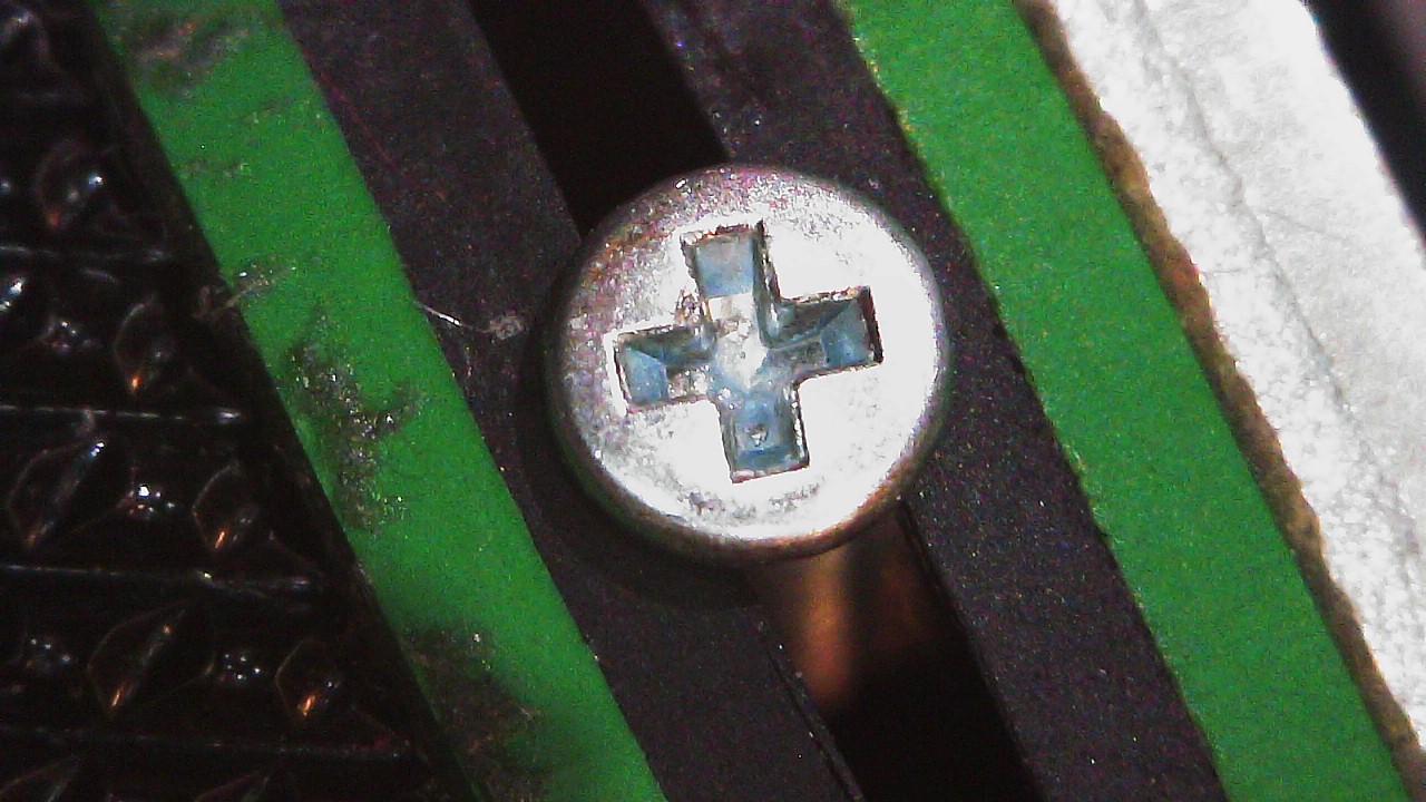
All Screws within the New 3DS have a JIS head (I assume JIS #00), but a Phillips #00 works. The Battery Door can be opened with a #00, but a #0 fits better.
There are three Tri-Wing screws. I suppose there is a JIS equivalent, but I haven't looked into it. IFixIt recommends the use of a "Y0" Tri-Wing driver. The Tri-point bit I used had a different measuring scheme and a Y1.5 worked for me (not sure why, but that isn't important). I believe the Y1.5 is equivalent to a Y00 which, again, worked for me.
Below is the list of screws and Hardware grouped by size.
I'll add links to an IFixIt Guide to match my terms to pictures (i.e. Motherboard Screw would point to the Motherboard removal step of an IFixIt guide). The screw names themselves will have a link to the image of the screw removal with another link next to it just in case that link dies.
Screws
Legend:
- Screw Length x Thread Width x Head Width.
- Recommended Driver.
- Screw Amounts, Placeholder name, and Link to IFixIt guides and images.
- Repeated previous entry as needed.
- Thread Pitch Measurement.
2mm x 1.5mm x 2.5mm
Phillips: PH #00
(3x)Small Circle Pad Screws (Step 10)
M1.4 – 0.4 x 1.5mm
2.5mm x 1.5mm x 2.5mm
Phillips: PH #00
(1x) Volume Slider Screw (No Guide)
(1x) 3D Slider Screw (No Guide)
(4x) D-pad Screws (Step 12)
(4x) Power Board Screws (Step 10)
M1.4 – 0.6 x 2mm
3mm x 1.5mm x 2.5mm
Phillips: PH #00
(4x) Gamecard Slot Screws (Step 12)
(2x) Motherboard Screws (IMAGE IS INCORRECT AS THERE ARE ONLY 2 MOTHERBOARD SCREWS. More information below) (Step 15)
M1.4 – 0.6 x 2.5mm
3.5mm x 1.5mm x 2.5mm
Phillips: PH #00
(6x) Top Screen Screws (No Guide)
(4x) Shoulder Button Screws (No Guide)
(1x) Power Button Screw (No Guide)
(1x) IR Blaster Screw (No Guide)
M1.4 – 0.6 x 3mm
3.5mm x 1.5mm x 2.5mm
Tri-Point: Y1.5/Y00
(3x) Micro SD Slot Cover Screws (Tri-Wing) (Step 4)
M1.4 – 0.6 x 3mm
3.5mm x 1.5mm x 4mm
Phillips: PH #0
(2x) Battery Door Screws (Step 1)
M1.4 – 0.4 x 3mm
6mm x 1.5mm x 2.5mm
Phillips: PH #00
(7x) Bottom Shell Screws (Step 7)
M1.4 – 0.6 x 5.5mm
7.5mm x 1.5mm x 2.5mm
Phillips: PH #00
(2x) Circle Pad Screws (Step 10)
M1.4 – 0.6 x 7mm
Other
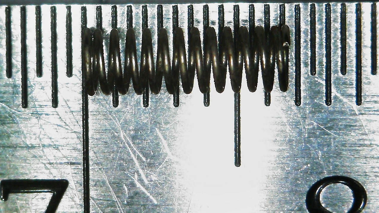
2x Shoulder Button Springs
6.5mm Length x 2mm Diameter
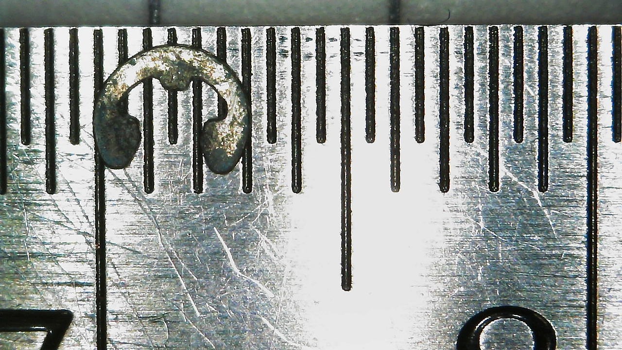
2x E-clip
3mm Width
2x Battery Door Nut
3mm Square x 1mm Thick
Screw Covers
(4x) Screw Covers: Two Feet and Two Top Screen
2.5mm Tall x 4mm Diameter
Battery Door

Two Battery Door Screws
M1.4 – 0.4 x 3mm
3.5mm x 1.5mm x 4mm
Phillips: PH #0
Two E-Clips
3mm Wide
Micro SD Slot Cover
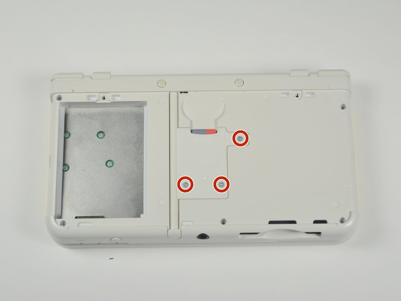
Three Tri-Wing Micro SD Slot Cover Screws
M1.4 – 0.6 x 3mm
3.5mm x 1.5mm x 2.5mm
Tri-Point: Y1.5/Y00
Bottom Shell

Seven Bottom Shell Screws
M1.4 – 0.6 x 5.5mm
6mm x 1.5mm x 2.5mm
Phillips: PH #00
Circle Pad
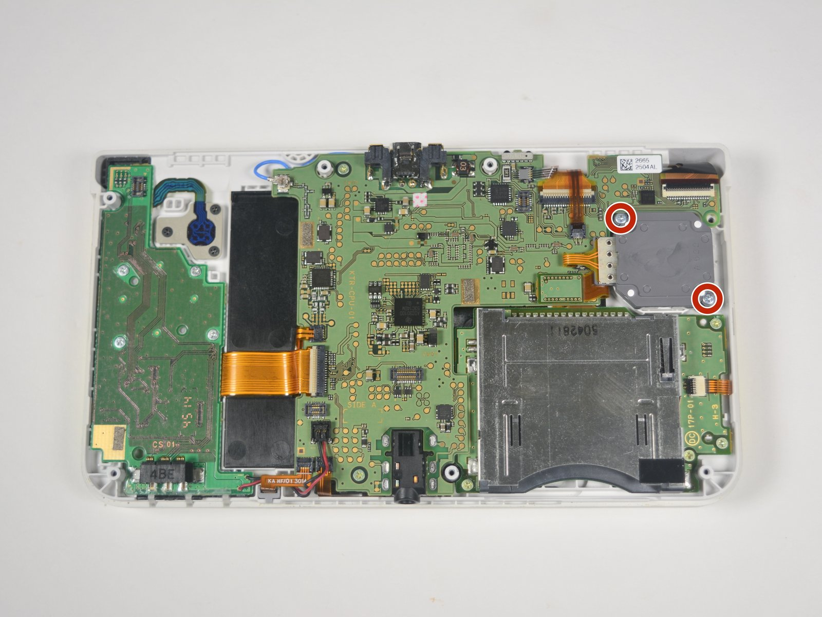
Two Circle Pad Screws
M1.4 – 0.6 x 7mm
7.5mm x 1.5mm x 2.5mm
Phillips: PH #00
Gamecard Slot
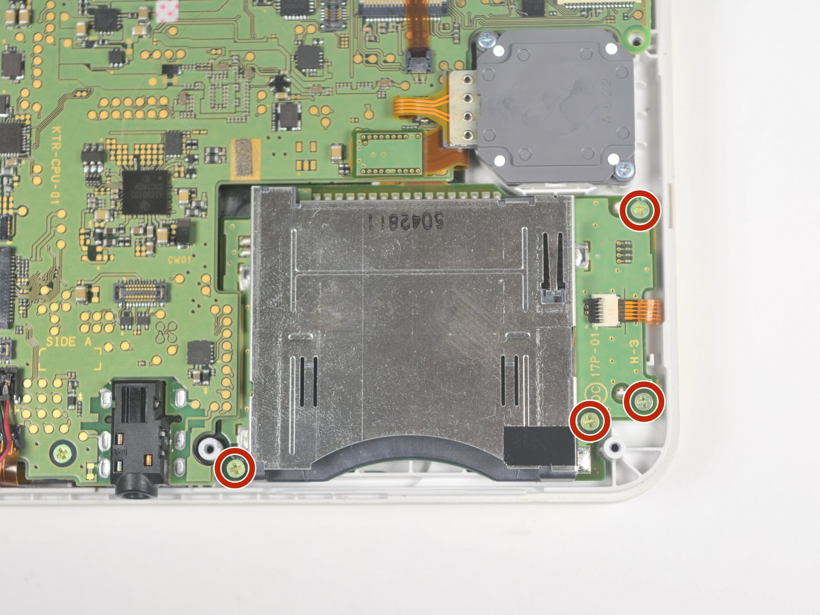
Four Gamecard Slot Screws
M1.4 – 0.6 x 2.5mm
3mm x 1.5mm x 2.5mm
Phillips: PH #00
D-Pad
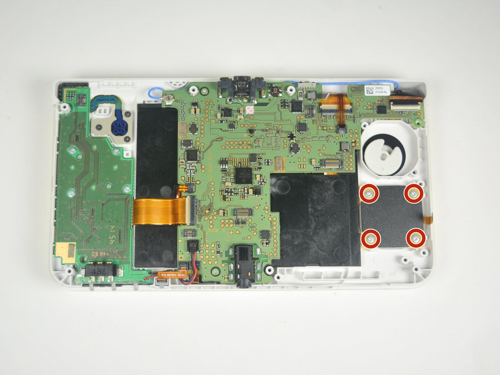
Four D-Pad Screws
M1.4 – 0.6 x 2mm
2.5mm x 1.5mm x 2.5mm
Phillips: PH #00


Power Board and Small Circle Pad
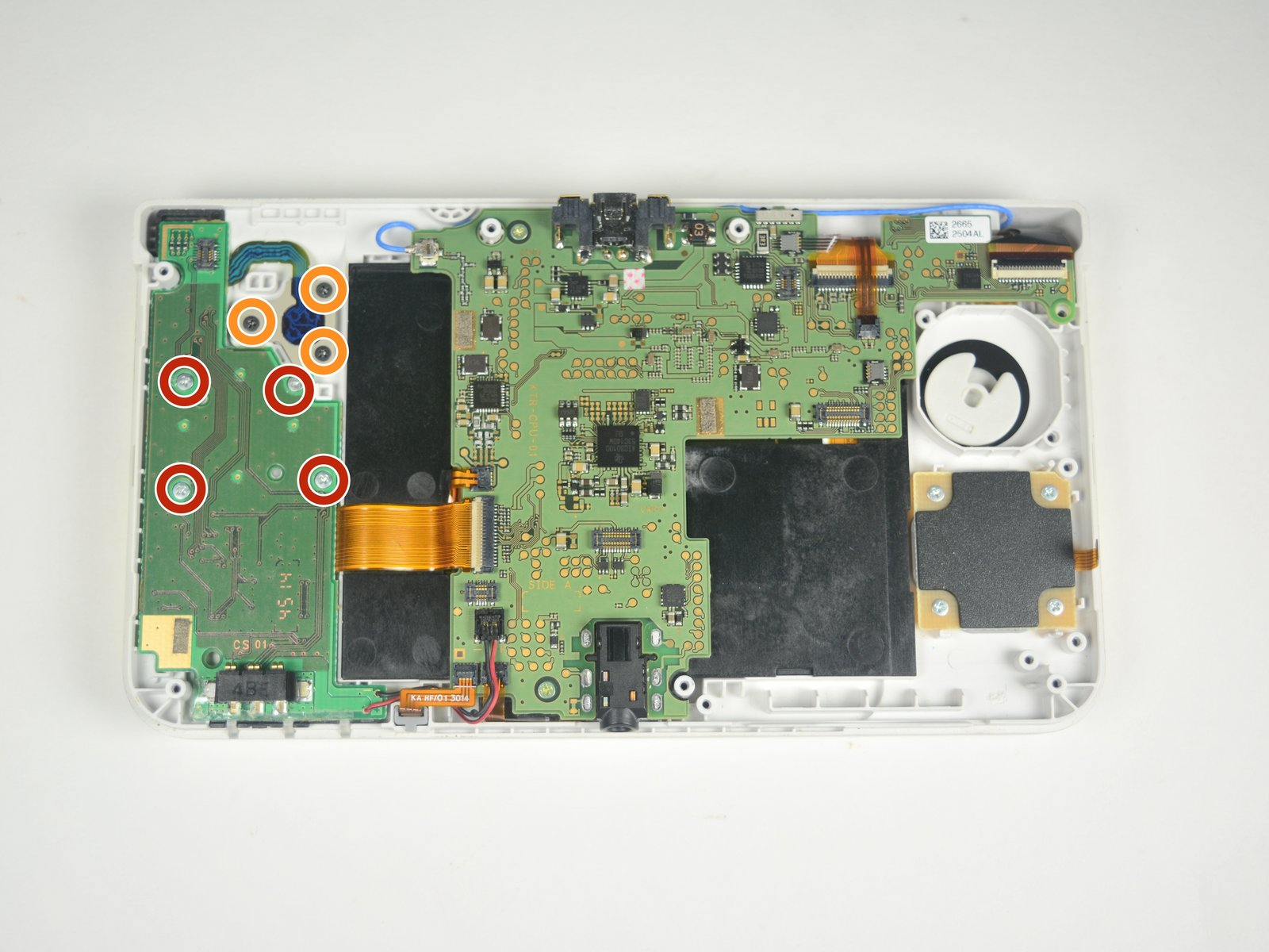
Four Power Board Screws
M1.4 – 0.6 x 2mm
2.5mm x 1.5mm x 2.5mm
Phillips: PH #00


Three Small Circle Pad Screws (Or whatever Nintendo called this nipple)
M1.4 – 0.4 x 1.5mm
2mm x 1.5mm x 2.5mm
Phillips: PH #00
Motherboard
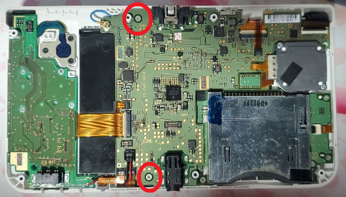
Two Motherboard Screws
M1.4 – 0.6 x 2.5mm
3mm x 1.5mm x 2.5mm
Phillips: PH #00


Top Shell
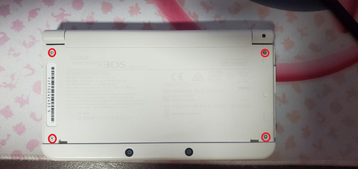
Six Top Screen Screws
M1.4 – 0.6 x 3mm
3.5mm x 1.5mm x 2.5mm
Phillips: PH #00
Volume and 3D Slider

Two Screws: Volume and 3D Slider
M1.4 – 0.6 x 2mm
2.5mm x 1.5mm x 2.5mm
Phillips: PH #00
Bottom Housing

Six Screws: Four for the Shoulder Buttons, and One each for the Power Button and IR Blaster.
M1.4 – 0.6 x 3mm
3.5mm x 1.5mm x 2.5mm
Phillips: PH #00

Two Shoulder Button Springs
6.5mm Length x 2mm Diameter
Two Battery Door Nuts
3mm Square x 1mm Thick
Screw Covers
Four Screw Covers: Two Feet and Two Top Screen
2.5mm Tall x 4mm Diameter
I measured the screws on a ruler with markings down to half-millimeter increments and a digital microscope. Measurements were taken similar to this image of measuring Thread Pitch below.
(Image Sourced from Albany County Fasteners' video, How to Measure Screws & Bolts - US & Metric Sizing | Fasteners 101)
Since I do not have specialty equipment to measure screws this small, I am forced to estimate; especially on the thread pitch itself. Take the measurements with the knowledge that it was done by someone who is a novice in screw measuring.
New 3DS
All Screws within the New 3DS have a JIS head (I assume JIS #00), but a Phillips #00 works. The Battery Door can be opened with a #00, but a #0 fits better.
There are three Tri-Wing screws. I suppose there is a JIS equivalent, but I haven't looked into it. IFixIt recommends the use of a "Y0" Tri-Wing driver. The Tri-point bit I used had a different measuring scheme and a Y1.5 worked for me (not sure why, but that isn't important). I believe the Y1.5 is equivalent to a Y00 which, again, worked for me.
Below is the list of screws and Hardware grouped by size.
I'll add links to an IFixIt Guide to match my terms to pictures (i.e. Motherboard Screw would point to the Motherboard removal step of an IFixIt guide). The screw names themselves will have a link to the image of the screw removal with another link next to it just in case that link dies.
Screws
Legend:
- Screw Length x Thread Width x Head Width.
- Recommended Driver.
- Screw Amounts, Placeholder name, and Link to IFixIt guides and images.
- Repeated previous entry as needed.
- Thread Pitch Measurement.
2mm x 1.5mm x 2.5mm
Phillips: PH #00
(3x)Small Circle Pad Screws (Step 10)
M1.4 – 0.4 x 1.5mm
2.5mm x 1.5mm x 2.5mm
Phillips: PH #00
(1x) Volume Slider Screw (No Guide)
(1x) 3D Slider Screw (No Guide)
(4x) D-pad Screws (Step 12)
(4x) Power Board Screws (Step 10)
M1.4 – 0.6 x 2mm
3mm x 1.5mm x 2.5mm
Phillips: PH #00
(4x) Gamecard Slot Screws (Step 12)
(2x) Motherboard Screws (IMAGE IS INCORRECT AS THERE ARE ONLY 2 MOTHERBOARD SCREWS. More information below) (Step 15)
M1.4 – 0.6 x 2.5mm
3.5mm x 1.5mm x 2.5mm
Phillips: PH #00
(6x) Top Screen Screws (No Guide)
(4x) Shoulder Button Screws (No Guide)
(1x) Power Button Screw (No Guide)
(1x) IR Blaster Screw (No Guide)
M1.4 – 0.6 x 3mm
3.5mm x 1.5mm x 2.5mm
Tri-Point: Y1.5/Y00
(3x) Micro SD Slot Cover Screws (Tri-Wing) (Step 4)
M1.4 – 0.6 x 3mm
3.5mm x 1.5mm x 4mm
Phillips: PH #0
(2x) Battery Door Screws (Step 1)
M1.4 – 0.4 x 3mm
6mm x 1.5mm x 2.5mm
Phillips: PH #00
(7x) Bottom Shell Screws (Step 7)
M1.4 – 0.6 x 5.5mm
7.5mm x 1.5mm x 2.5mm
Phillips: PH #00
(2x) Circle Pad Screws (Step 10)
M1.4 – 0.6 x 7mm
Other
2x Shoulder Button Springs
6.5mm Length x 2mm Diameter
2x E-clip
3mm Width
2x Battery Door Nut
3mm Square x 1mm Thick
Screw Covers
(4x) Screw Covers: Two Feet and Two Top Screen
2.5mm Tall x 4mm Diameter
Battery Door
Two Battery Door Screws
M1.4 – 0.4 x 3mm
3.5mm x 1.5mm x 4mm
Phillips: PH #0
Two E-Clips
3mm Wide
Micro SD Slot Cover
Three Tri-Wing Micro SD Slot Cover Screws
M1.4 – 0.6 x 3mm
3.5mm x 1.5mm x 2.5mm
Tri-Point: Y1.5/Y00
Bottom Shell
Seven Bottom Shell Screws
M1.4 – 0.6 x 5.5mm
6mm x 1.5mm x 2.5mm
Phillips: PH #00
Circle Pad
Two Circle Pad Screws
M1.4 – 0.6 x 7mm
7.5mm x 1.5mm x 2.5mm
Phillips: PH #00
Gamecard Slot
Four Gamecard Slot Screws
M1.4 – 0.6 x 2.5mm
3mm x 1.5mm x 2.5mm
Phillips: PH #00
D-Pad
Four D-Pad Screws
M1.4 – 0.6 x 2mm
2.5mm x 1.5mm x 2.5mm
Phillips: PH #00
Power Board and Small Circle Pad
Four Power Board Screws
M1.4 – 0.6 x 2mm
2.5mm x 1.5mm x 2.5mm
Phillips: PH #00
Three Small Circle Pad Screws (Or whatever Nintendo called this nipple)
M1.4 – 0.4 x 1.5mm
2mm x 1.5mm x 2.5mm
Phillips: PH #00
Motherboard
Two Motherboard Screws
M1.4 – 0.6 x 2.5mm
3mm x 1.5mm x 2.5mm
Phillips: PH #00
Top Shell
Six Top Screen Screws
M1.4 – 0.6 x 3mm
3.5mm x 1.5mm x 2.5mm
Phillips: PH #00
Volume and 3D Slider
Two Screws: Volume and 3D Slider
M1.4 – 0.6 x 2mm
2.5mm x 1.5mm x 2.5mm
Phillips: PH #00
Bottom Housing
Six Screws: Four for the Shoulder Buttons, and One each for the Power Button and IR Blaster.
M1.4 – 0.6 x 3mm
3.5mm x 1.5mm x 2.5mm
Phillips: PH #00
Two Shoulder Button Springs
6.5mm Length x 2mm Diameter
Two Battery Door Nuts
3mm Square x 1mm Thick
Screw Covers
Four Screw Covers: Two Feet and Two Top Screen
2.5mm Tall x 4mm Diameter
How I Measure Screws.
Measurements done with Calipers will only be done on one screw per category, and will be subject to some amount of inaccuracies due to the size of the screws and the tools I have. Measurements like Thread Pitch, Shank Length, Thread Length, and Recess Width are done by eyeballing it with my calipers and a microscope. Measurements like Thread Diameter and Screw Length will be far more accurate as I can physically clamp them in my calipers.
Resources, Set Up, and Drivers.
Screws will be sorted by size, going from shortest to longest, rounded to the nearest 0.5mm. In the cases where screws weren't rounded to the whole or half steps, I found their measurements consistent with other screws of the same category, thus, were labeled with their non-standard measurement.I'll add links to an IFixIt Guide to match my terms to pictures (i.e., Motherboard Screw would point to the Motherboard removal step of an IFixIt guide). If there is no guide, I won't be able to link.
The New 3DS guides on IFixIt are not complete as they do not include a step for removing the Top Screen. The drivers recommended in the guide match my experience, so I have nothing to say there.
The only gripe I have with the guides is that the Motherboard removal step says there are three screws; however, there aren't. The screw circled on the top right, next to the top display and camera ribbon connector, is a through hole for one of the bottom shell screws. Screwing a motherboard screw there MAY be ok, but what it will do is plug the hole for the screw that belongs there.
Screws
2.25 mm Black Screw. Fine Thread. Cross Recess #00
- (3x) Small Circle Pad Screws (Step 10)
Caliper Measurements
- A: 2.25 mm
- B: 1.24 mm
- C: 0.39 mm
- D: 0.22 mm
- E: 1.47 mm
- F: 0.17 mm
- G: 2.41 mm
- X Recess: 1.49 mm (#00)
2.50 mm Silver Screw. Coarse Thread. Cross Recess #00
- (1x) Volume Slider Screw (No Guide)
- (1x) 3D Slider Screw (No Guide)
- (4x) D-pad Screws (Step 12)
- (4x) Power Board Screws (Step 10)
Caliper Measurements
- A: 2.49 mm
- B: 1.73mm
- C: 0.37 mm
- D: 0.34 mm
- E: 1.46 mm
- F: 0.19 mm
- G: 2.44 mm
- X Recess: 1.45 mm (#00)
3.00 mm Gold Screw. Coarse Thread. Cross Recess #00
- (4x) Gamecard Slot Screws (Step 12)
- (2x) Motherboard Screws (IMAGE IS INCORRECT AS THERE ARE ONLY 2 MOTHERBOARD SCREWS.) (Step 15)
Caliper Measurements
- A: 3.05 mm
- B: 2.15 mm
- C: 0.52 mm
- D: 0.46 mm
- E: 1.40 mm
- F: 0.22 mm
- G: 2.44 mm
- X Recess: 1.52 mm (#00)
3.50 mm Silver Screw. Coarse Thread. Cross Recess #00
- (6x) Top Screen Screws (No Guide)
- (4x) Shoulder Button Screws (No Guide)
- (1x) Power Button Screw (No Guide)
- (1x) IR Blaster Screw (No Guide)
Caliper Measurements
- A: 3.5 mm
- B: 2.63 mm
- C: 0.58 mm
- D: 0.36 mm
- E: 1.40 mm
- F: 0.18 mm
- G: 2.51 mm
- X Recess: 1.51 mm (#00)
3.50 mm Silver Screw. Coarse Thread. Y Type 1/#0
Caliper Measurements
- A: 3.56 mm
- B: 2.35 mm
- C: 0.41 mm
- D: 0.52 mm
- E: 1.39 mm
- F: 0.22 mm
- G: 2.47 mm
- X Recess 1.13 mm
4.00 mm Silver or Black Screw. Machine Thread Unique. Cross Recess #1
- (2x) Battery Door Screws (Step 1)
Caliper Measurements
- A: 3.74 mm
- B: 1.39 mm
- C: 1.49 mm
- D: 0.31 mm
- E: 1.53 mm
- F: 0.30 mm
- G: 3.90 mm
- X Recess: 2.17 (#1 fit the best, but these screws are a little worn)
6.30 mm Silver Screw. Coarse Thread. Cross Recess #00
- (7x) Bottom Shell Screws (Step 7)
Caliper Measurements
- A: 6.30 mm
- B: 5.12 mm
- C: 0.31 mm
- D: 0.44 mm
- E: 1.40 mm
- F: 0.51 mm
- G: 2.50 mm
- X Recess: 1.56 mm (#00)
7.80 mm Silver Screw. Coarse Thread. Cross Recess #00
- (2x) Circle Pad Screws (Step 10)
Caliper Measurements
- A: 7.75 mm
- B: 6.80 mm
- C: 0.34 mm
- D: 0.47 mm
- E: 1.39 mm
- F: 0.46 mm
- G: 2.51 mm
- X Recess: 1.49mm #00
E- Clip
Caliper Measurements
- Thickness 0.35 mm
- Width 3.22 mm
- Height 2.57 mm
Battery Door Nut
Caliper Measurements
- Height/Width - 3.07 mm
- Thickness – 1.01 mm
Spring
Caliper Measurements
- Length - 6.75 mm
- Diameter - 2.21 mm
Screw Covers
Caliper Measurements
- Height - 3.92 mm
- Diameter - 2.6 mm
Last edited by KIlly728,


