Hardware Hacking Need some help to fix a problem during a failed Hwfly lite installation

Z3nmuron

Member
OP
Newcomer
Joined
May 23, 2022
Messages
10
Trophies
0
Age
35
Location
Leme
XP
55
Country
Brazil
First of all, hello to everyone, I’d like to ask for some advices, if someone could spare some time.
Well, I tried installing a Hwfly modchip to my switch lite. Did all the soldering points and everything seemed to be alright. When I tried turning on, the chip’s led blinked purple for some seconds, then went red and off. The switch wasn’t turning on, even in OFW, there wasn’t any life signal.
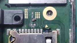
I decided to check the soldering points to see if any of them could be with a bad joint, but when I tried moving the chip down to check the flex above the processor, it went off and ripped the 3.3v capacitor with it…
Well, as bad as things already are, I believe I can put it back in place. Just asked for some new pads so I can do a decent job there.
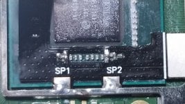
While i was waiting for these things to arrive, I took off the flex on SP1 and SP2 to try and find why it wasn’t booting even in OFW before the cap went off.
And well, the caps are giving some strange readings, but it’s weird, because I only soldered the points in SP1 and SP2, I don’t know why almost all of the caps in the shield are giving these wrong readings.
If anyone could share some light with me, I’d be glad, as I don’t have a deep knowledge of these more complex issues. I fixed some consoles already, an old gamecube and an Xbox 360 of mine that wasn’t turning on as well.
Btw, I’ve seen a schematic with the readings of these components around the web, but for the original model of the switch. I have advanced knowledge in Corel draw and Photoshop, so if anyone is up to make a map with these components and its readings, I’d be glad to help. Just send me a rough sketch with the readings, and I can take care of the rest. Since it’s pretty hard to find these kind of materials for the switch specially the lite and oled models.
Well, thanks for anyone who can share some light on the problem.
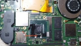
I'll be leaving some pictures of the readings I got, I did it on diode mode, with red probe on ground, and black probe on each site of the terminals. The green ones didn't return the beep, and all of the black ones did. I know the the ones who didn't beep in one of the sides is a good cap, theoretically, but I'm leaving the explanation in case someone wonder why the different colors.
There is as well a pic with the SP1 and SP2 points still soldered, and the ripped 3.3v cap, which I'll be trying to replace.
Thanks to anyone who can share some light on the issue.
 

Attachments

  • SAVE_20220605_154116.jpg
    SAVE_20220605_154116.jpg
    578.9 KB · Views: 225
  • IMG_20220521_143641.jpg
    IMG_20220521_143641.jpg
    2.4 MB · Views: 282
  • IMG_20220521_143707.jpg
    IMG_20220521_143707.jpg
    2.7 MB · Views: 245
  • IMG_20220521_143821.jpg
    IMG_20220521_143821.jpg
    2.8 MB · Views: 250

de9ed

Well-Known Member
Member
Joined
Oct 22, 2020
Messages
278
Trophies
0
Age
30
XP
919
Country
Canada
The apu value looks ok. Show you solder joint on the other flex cable above the APU ? Looks like your 3.3v capacitor broke. You would need a new one. I don't have a lite on hand to measure the value for you.
 

Z3nmuron

Member
OP
Newcomer
Joined
May 23, 2022
Messages
10
Trophies
0
Age
35
Location
Leme
XP
55
Country
Brazil
The apu value looks ok. Show you solder joint on the other flex cable above the APU ? Looks like your 3.3v capacitor broke. You would need a new one. I don't have a lite on hand to measure the value for you.
I dessoldered the other flex as well. While I was taking it out, a pad came out and i discarded it because I didn't want to jumper it. I asked for another one to replace it.
As for the capacitor, I didn't lost the one that came off, is there any possibility it is still good? Then I wouldn't have to look for a substitute. I may even take the measurements of it and post it here, in case someone else needs this info.
Now the part that is annoying me, do you have any idea why the console wasn't booting after I installed the chip? The cap was in place at that time, so even if the chip wouldn't be flashing the console, it would still boot to OFW normally, wouldn't it? I searched for this info in a lot of places but couldn't find a concrete answer.
 

de9ed

Well-Known Member
Member
Joined
Oct 22, 2020
Messages
278
Trophies
0
Age
30
XP
919
Country
Canada
I dessoldered the other flex as well. While I was taking it out, a pad came out and i discarded it because I didn't want to jumper it. I asked for another one to replace it.
As for the capacitor, I didn't lost the one that came off, is there any possibility it is still good? Then I wouldn't have to look for a substitute. I may even take the measurements of it and post it here, in case someone else needs this info.
Now the part that is annoying me, do you have any idea why the console wasn't booting after I installed the chip? The cap was in place at that time, so even if the chip wouldn't be flashing the console, it would still boot to OFW normally, wouldn't it? I searched for this info in a lot of places but couldn't find a concrete answer.

Is it charged ? And does backlight get voltage ? Hopefully not eMMC issue
 

Z3nmuron

Member
OP
Newcomer
Joined
May 23, 2022
Messages
10
Trophies
0
Age
35
Location
Leme
XP
55
Country
Brazil
Is it charged ? And does backlight get voltage ? Hopefully not eMMC issue
Yes, the battery was on 100% when I disassembled it. I just didn't measure the backlight though, if you can spot the place to me, I can do the measurements once I place back the 3.3v cap.
Also, when I turned it on to test the hwfly, I didn't had the SD card with hekate in the slot. Is it necessary for the testing and to get the green led?
 

de9ed

Well-Known Member
Member
Joined
Oct 22, 2020
Messages
278
Trophies
0
Age
30
XP
919
Country
Canada
Yes, the battery was on 100% when I disassembled it. I just didn't measure the backlight though, if you can spot the place to me, I can do the measurements once I place back the 3.3v cap.
Also, when I turned it on to test the hwfly, I didn't had the SD card with hekate in the slot. Is it necessary for the testing and to get the green led?
the backlight is the FPC second from the top on the right-hand side daughter board.

when successful glitch, it should show green LED then off. Newer Lite sometime do not have the NO SD screen
 

Z3nmuron

Member
OP
Newcomer
Joined
May 23, 2022
Messages
10
Trophies
0
Age
35
Location
Leme
XP
55
Country
Brazil
the backlight is the FPC second from the top on the right-hand side daughter board.

when successful glitch, it should show green LED then off. Newer Lite sometime do not have the NO SD screen
You mean this one in the image?
I shall test the pads on it, or some terminal next to it?
As for the chip, if it should stay green in the end, even without the SD on slot, then in fact something went wrong.
Well, the new flex cable for the chip arrived, just waiting the new pads to get back on it.
 

Attachments

  • images-13.jpeg
    images-13.jpeg
    43.3 KB · Views: 244

de9ed

Well-Known Member
Member
Joined
Oct 22, 2020
Messages
278
Trophies
0
Age
30
XP
919
Country
Canada
You mean this one in the image?
I shall test the pads on it, or some terminal next to it?
As for the chip, if it should stay green in the end, even without the SD on slot, then in fact something went wrong.
Well, the new flex cable for the chip arrived, just waiting the new pads to get back on it.

The backlight is on the daughter board on the right side ( looking from the back of the switch)

Does the switch turn on when everything is removed ?
 

Z3nmuron

Member
OP
Newcomer
Joined
May 23, 2022
Messages
10
Trophies
0
Age
35
Location
Leme
XP
55
Country
Brazil
The backlight is on the daughter board on the right side ( looking from the back of the switch)

Does the switch turn on when everything is removed ?
Well, I took the switch to try the repair, and the 3.3v cap is really damaged, I'll need to replace it. Do you have the info on its values?
Btw, when you ask if the switch turn on when everything is removed, you mean the modchip and its cables? For I couldn't try turning it on after I desoldered the cables because of the capacitor that went off. I'm trying to fix it first and then I'll try turning it on without the modchip and the flex cables to see if everything goes well.
 

Switxh

Well-Known Member
Member
Joined
Mar 11, 2023
Messages
110
Trophies
0
Age
28
XP
273
Country
United Kingdom
Well, I took the switch to try the repair, and the 3.3v cap is really damaged, I'll need to replace it. Do you have the info on its values?
Btw, when you ask if the switch turn on when everything is removed, you mean the modchip and its cables? For I couldn't try turning it on after I desoldered the cables because of the capacitor that went off. I'm trying to fix it first and then I'll try turning it on without the modchip and the flex cables to see if everything goes well.
The capacitor is 0402 size, 4.7uF rated for 10v. You don't need that capacitor to power on the Switch. It's just a filtering capacitor for the SD card. It doesn't do anything else. Switch will still power on fully. Just make sure NO SD card is in the slot or it will only show a black screen with backlight on. You don't need to replace that cap to test the switch.

Also what are you talking about when you refer to "ordering pads"? If the pad on the left of the capacitor is missing you can just expose more of the PCB above or below the pad and solder the cap at an angle and it will work perfectly fine as the positive layer is directly under the green solder mask all around the left side of the cap.


Edit: my bad just noticed this is a year old. Not even sure how i got here to be honest.
 

Site & Scene News

Popular threads in this forum

General chit-chat
Help Users
  • No one is chatting at the moment.
    Veho @ Veho: The cybertruck is a death trap.