Curious how this chip is compared to the white board that some people have issues with the ground plane. Are u located in USA I tried to order this board and they told me they won't sell to USA which is a bummer, trying to locate the black instinct if it's better designed than the white one
diode mode on multimeter to ground
Black lead to ground and red to each points
A/CMD = 0.709 v
B/RST = OL
C/DAT0 = 0.520v
D/ CLK = 0.514 v
3.3V = 0.679 v
SP 1 = 0.001 v 00.5 ohms
SP 2 = 0.001 v 00.3 ohms
I compared the values to @ranma99vn on page 4
Looks like my SP1 and SP2 values are out by quite a bit
Pulled of the CPU cover and now saw there is a solder bridge between SP2 points covering the capacitor
Will try to correct this tonight
Dam, thats concerning.
So leaving the CPU (SP1 and SP2) connected, wont cause cause the board not to boot?
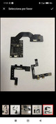
I only soldered the 6 points on the board
CPU
CLK
CMD
3.3v
Dat0
RST
I'll check again and post some photos of the board
Post automatically merged:
I did the measurements again:
diode mode on multimeter to ground
Black lead to ground and red to each points
A/CMD = 0.709 v
B/RST = OL
C/DAT0 = 0.520v
D/ CLK = 0.514 v
3.3V = 0.679 v
SP 1 = 0.001 v 00.5 ohms
SP 2 = 0.001 v 00.3 ohms
I compared the values to @ranma99vn on page 4
Looks like my SP1 and SP2 values are out by quite a bit
Pulled of the CPU cover and now saw there is a solder bridge between SP2 points covering the capacitor
Will try to correct this tonight
Thanks @doom95, I corrected the solder bridge/short and re-installed the modchip.
Now the modship sometimes it boots into the no sd card screen, i think it did the initial training and now it also sometimes it boots to OFW and the red blinking lights (7-8 blinks at a time appears) - the red lights appear more often.
I measured the values when the everything is connected and running.
I get 3.3v, 1.7v, 1.1v
I can try to run putty, just looking for the download link to putty.
Thanks, I corrected the short, now its starting to OFW.
Back to installing the modship!
Post automatically merged:
Thanks @doom95, I corrected the solder bridge/short and re-installed the modchip.
Now the modship sometimes it boots into the no sd card screen, i think it did the initial training and now it also sometimes it boots to OFW and the red blinking lights (7-8 blinks at a time appears) - the red lights appear more often.
I measured the values when the everything is connected and running.
I get 3.3v, 1.7v, 1.1v
I can try to run putty, just looking for the download link to putty.
Apologies, I have installed it but not sure how to use it.
Do I have to disconnect the battery from the switch before i connect the USB cable to modchip?
Curious how this chip is compared to the white board that some people have issues with the ground plane. Are u located in USA I tried to order this board and they told me they won't sell to USA which is a bummer, trying to locate the black instinct if it's better designed than the white one
Curious how this chip is compared to the white board that some people have issues with the ground plane. Are u located in USA I tried to order this board and they told me they won't sell to USA which is a bummer, trying to locate the black instinct if it's better designed than the white one
That's where I found the chip, only found 1 seller with the black instinct chip and he won't sell to America. I'd rather not do a picofly would like the instinct chip as it seems the best to install.
Looks like I found the hwfly but unless I misread something that dat0 cable for the hwfly needs the emmc reflowed whereas the instinct is a pressure fit so to speak.
Not sure. That's what I was asking about, I know some people reported ground plane issues with the white board. At this point it's likely irrelevant as I can only find 1 shop on ali with the black board and he won't sell to America
Brudi.....
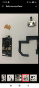
Like i said something is/was shorted to GND. The solder points on the Modchip didn't look good either...
Clean the points on the Modchip and put a small solder blob on, to prevent shorts to GND. The B Point solder with hanging out strains from the cable didn't look good to...
Use a small tip or let someone do it with the needed skill.
Everything went super smoothly. All the cables provided had been used.
Super clean installation, only takes 2 flying wires. I used AWG34 enameled wire, they were DAT0 and RESET.
Bare in mind that the RST pin in the OLED version gives an open circuit. I lost 2h trying to understand it haha.
The capacitors on the cpu package will read about 18/20ohm each. If you read about 10ohm, it means two are shorted together.
Now Doing an EMMC backup and so far so good.
Injection times are ridiculously fast.
I hope to see +99fps with the Kryonaut lol.
If you're going to use an expensive thermal paste I'd go a bit further and remove that nasty film they stuck on top of the CPU so to make direct contact to the heatsink. I think this film drastically worsen thermal conductivity.
The seller told me that so far the firmware used cannot be upgraded but to work ATM it doesn't need to.
I think he simply ment that there are no updates.
Moreover he strongly advise AGAINST the lite version. "It's bugged".
The seller told me that so far the firmware used cannot be upgraded but to work ATM it doesn't need to.
I think he simply ment that there are no updates.
Moreover he strongly advise AGAINST the lite version. "It's bugged".
Very tempted to buy the rp2040 oled with cables (seeing as the hwfly chip i bought went awol), just concerned that something new will be -right around the corner-
If you're going to use an expensive thermal paste I'd go a bit further and remove that nasty film they stuck on top of the CPU so to make direct contact to the heatsink. I think this film drastically worsen thermal conductivity.
Post automatically merged:
Check your diode readings. Also check reverse polarity on your dat0.
same readings effectively, I have made a post with detailed photos and a video similar to yours, im not going to post here but if you want to reference to see if there is anything different to mine, i guess it will all te the same to get the same error light
Sony made a shocking announcement today, revealing that the company plans to move away from physical game releases in the future. Citing claims of how the industry is...
After much speculation, a lot of which being caused by dbrand's unceremonious reveal of their Companion Cube casing, the Steam Machine is finally available to order...
Remember when you could get an Xbox Series S for $300? Those were the days. Microsoft has today announced the latest in their console price hikes, seeing their...
Since being decompiled Super Mario 64 has seen a considerable amount of interest. We've had multiple PC ports, but the efforts beyond that are really astounding. It's...
Happy June 15th! Well, this one was close enough. Atmosphere has been updated to add support for the latest Nintendo Switch firmware, 22.5.0. This means all of you...
The delays may be behind us, but the news isn't all good for Grand Theft Auto VI. Rockstar have today announced that pre-orders for the game will go live tomorrow, on...
It's that time again. Batten down the hatches and ride out the storm, because we've got another Switch update! And Switch 2, but that's somewhat less impactful given...
Last month we got confirmation of a new model of Switch 2 to better comply with upcoming EU regulations. With the legislation set to come into effect in February of...
The end has come for the PlayStation 3 and the PlayStation Vita. After supporting the PSN Store on the PS3 and PS Vita since 2006 and 2011 respectively, Sony has...
With many a fantastic port under their belts, Harbour Masters return with a brand new project dubbed Lighthouse. Set to release next month, it'll once again throw...
Sony made a shocking announcement today, revealing that the company plans to move away from physical game releases in the future. Citing claims of how the industry is...
After much speculation, a lot of which being caused by dbrand's unceremonious reveal of their Companion Cube casing, the Steam Machine is finally available to order...
Remember when you could get an Xbox Series S for $300? Those were the days. Microsoft has today announced the latest in their console price hikes, seeing their...
The delays may be behind us, but the news isn't all good for Grand Theft Auto VI. Rockstar have today announced that pre-orders for the game will go live tomorrow, on...
Last month we got confirmation of a new model of Switch 2 to better comply with upcoming EU regulations. With the legislation set to come into effect in February of...
The end has come for the PlayStation 3 and the PlayStation Vita. After supporting the PSN Store on the PS3 and PS Vita since 2006 and 2011 respectively, Sony has...
Tired of waiting for Game Freak to bring Pokemon Emerald to modern platforms? We've got you covered with a brand new port in the works. Currently available on GitHub...
Since being decompiled Super Mario 64 has seen a considerable amount of interest. We've had multiple PC ports, but the efforts beyond that are really astounding. It's...
Apple have today announced price increases, primarily focused on their MacBook and iPad lines. These increases have already come into effect, with both prices and the...
It's that time again. Batten down the hatches and ride out the storm, because we've got another Switch update! And Switch 2, but that's somewhat less impactful given...


")


