Hardware Gba sp ags 101

lory955

New Member
OP
Newbie
Joined
May 28, 2023
Messages
3
Trophies
0
Age
33
XP
46
Country
Italy
Hello to everyone
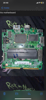
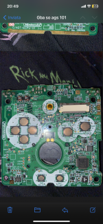
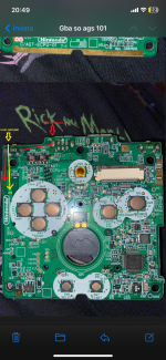
I was trying to install amp flex on my gba sp ags 101, but instead of a normal mainboard I have this one instead.
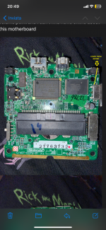
Vcc and sp point are at the same position as usual, ground in in a different place but it’s ok I can reach it by a fine wire.
I can’t find the volume point and that’s why I’m stuck.
Did someone have it and can help me?

My mainboard model seems to be C/AGT-ECPU-01
 

Attachments

  • IMG_2050.png
    IMG_2050.png
    5.2 MB · Views: 37
  • IMG_2051.png
    IMG_2051.png
    5.4 MB · Views: 37
  • image.jpg
    image.jpg
    3.9 MB · Views: 34
  • Like
Reactions: davinidae

davinidae

New Member
Newbie
Joined
Jan 14, 2024
Messages
2
Trophies
0
Age
26
XP
3
Country
Spain
I have found the same issue. There is no information about C/AGT-ECPU-01 online at all. Starting to think we are fucked.
 

lory955

New Member
OP
Newbie
Joined
May 28, 2023
Messages
3
Trophies
0
Age
33
XP
46
Country
Italy
I have found the same issue. There is no information about C/AGT-ECPU-01 online at all. Starting to think we are fucked.
Maybe it’s a later version of gba sp. Maybe manufactured last years of production. Still today I can’t find any specs about it.
 

davinidae

New Member
Newbie
Joined
Jan 14, 2024
Messages
2
Trophies
0
Age
26
XP
3
Country
Spain
Hey, I have been able to install the CleamAmp Pro on my GBA after manually researching and testing. Sorry because i can not post images or links since i'm a new account on this forum. Yes, it seems our motherboards are a very late model plus it's the AGS-101 model, so there is little to no info.

Nevertheless, the solution i've found is working as expected. Here are the instructions:

- We need to connect the VOL pin to the Volume Wheel's Pin Number 2 as this is the equivalent pin that AGS-001 use. It seems on AGS-101 all Volume pins are internal to the Volumen Wheel. You will need a thin cable that will go around the PCB from inside the L/R button, next to the pressing point. You will also have to trim the case on the side where the closest screw is at or the case won't close.

- We need to create a connection to Ground since there is none near D13. The closest one to D13 is P5 pin (top area of the PCB). The closest pin to P5 is an unnamed one on the L/R button. You will see there are 4 pins on the R/L button doing the following formation:

1 4
2 3

We want run a cable from P5 to pin 4. This is an unused pin connected to the (also unused) pin 1 on the other side of the R/L button. Then from pin 1 you run a cable to Ground on the mod.

Hope these instructions are clear enough.
Post automatically merged:

I am attaching the images, hope the go through...
Post automatically merged:

It seems they went through! Here is the photo also pointing out where you need to trim the plastic.
 

Attachments

  • IMG_2050.png
    IMG_2050.png
    2.9 MB · Views: 22
  • IMG_2051.png
    IMG_2051.png
    3 MB · Views: 19
  • IMG_2051.png
    IMG_2051.png
    2.5 MB · Views: 16
Last edited by davinidae,

Hropet

New Member
Newbie
Joined
Apr 17, 2024
Messages
1
Trophies
0
Age
26
XP
5
Country
Slovenia
Hey, I have been able to install the CleamAmp Pro on my GBA after manually researching and testing. Sorry because i can not post images or links since i'm a new account on this forum. Yes, it seems our motherboards are a very late model plus it's the AGS-101 model, so there is little to no info.

Nevertheless, the solution i've found is working as expected. Here are the instructions:

- We need to connect the VOL pin to the Volume Wheel's Pin Number 2 as this is the equivalent pin that AGS-001 use. It seems on AGS-101 all Volume pins are internal to the Volumen Wheel. You will need a thin cable that will go around the PCB from inside the L/R button, next to the pressing point. You will also have to trim the case on the side where the closest screw is at or the case won't close.

- We need to create a connection to Ground since there is none near D13. The closest one to D13 is P5 pin (top area of the PCB). The closest pin to P5 is an unnamed one on the L/R button. You will see there are 4 pins on the R/L button doing the following formation:

1 4
2 3

We want run a cable from P5 to pin 4. This is an unused pin connected to the (also unused) pin 1 on the other side of the R/L button. Then from pin 1 you run a cable to Ground on the mod.

Hope these instructions are clear enough.
Post automatically merged:

I am attaching the images, hope the go through...
Post automatically merged:

It seems they went through! Here is the photo also pointing out where you need to trim the plastic.
Hello,
I tried to modify this motherboard to usb-c charging. During modification i lost C90 capacitor. Do you maybe know its info so I can order spare? I am new at this and for the life of me I can not find anything online. I would really apriciate the help!
 

Site & Scene News

Popular threads in this forum

General chit-chat
Help Users
  • No one is chatting at the moment.
    K3Nv2 @ K3Nv2: Lol rappers still promoting crypto