Hey I hope I can find some help here, I'm really frustrated and can't find any solution to my problem.
A few things to know,
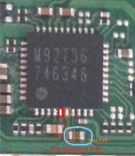
So I've taken the switch apart, desoldered the chip and measured all the caps around P13USB, M92T36 and BQ24193. But nothing, everything looks OK to me, no beeping and the caps seem to be fine.
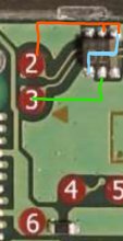
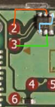
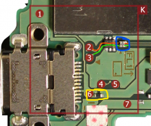
I've found out two things marked in the attached picture....
First when I measured the red and green line, there was no connection, so I desoldered the USB choke and put two wires on the red and green connections. So now I can measure a current of 4.2V on each wire, but the switch is still not turning on! (And I now have to order a new choke)
Second the yellow marked cap doesn't seem to have any resistance and doesn't seem to have an anode, when connecting either side with ground.
I'm really lost and I don't know what could be causing the problem, if anyone has any clue, it would be really appreciated!View attachment 265533
A few things to know,
- The switch has AutoRCM enabled
- An RCMx86 chip was soldered, but even after desoldering the switch doesn't work (Everything worked fine, before the problem happened)
- The battery reads 4.2V, I've charged it externally to be sure that the battery isn't causing the problem
So I've taken the switch apart, desoldered the chip and measured all the caps around P13USB, M92T36 and BQ24193. But nothing, everything looks OK to me, no beeping and the caps seem to be fine.
I've found out two things marked in the attached picture....
First when I measured the red and green line, there was no connection, so I desoldered the USB choke and put two wires on the red and green connections. So now I can measure a current of 4.2V on each wire, but the switch is still not turning on! (And I now have to order a new choke)
Second the yellow marked cap doesn't seem to have any resistance and doesn't seem to have an anode, when connecting either side with ground.
I'm really lost and I don't know what could be causing the problem, if anyone has any clue, it would be really appreciated!View attachment 265533
Attachments
Last edited by RathX,