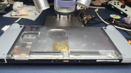
Just a quick one... I managed to find a place where the chip sits low enough so it doesn't bulge the case out...
I cut the top half of the ram shield off, left the APU side.
Took off the side rail the ram shield clips down onto. This leaves just enough space for the IC on the bottom of the Picofly to sit in between the group of Switch IC's in that area.
I then insulated the bottom of the Picofly PCB with a double layer of kapton tape.
The top part of the shield was cut away and kapton tape placed over to hold wiring and chip in place - and to insulate any top casing from coming into contact with the chip...
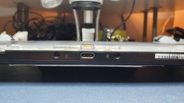
Just in case you need USB one day.
Up to you if you want to remove, but hey...")
I cut the top half of the ram shield off, left the APU side.
Took off the side rail the ram shield clips down onto. This leaves just enough space for the IC on the bottom of the Picofly to sit in between the group of Switch IC's in that area.
I then insulated the bottom of the Picofly PCB with a double layer of kapton tape.
The top part of the shield was cut away and kapton tape placed over to hold wiring and chip in place - and to insulate any top casing from coming into contact with the chip...
Just in case you need USB one day.
Up to you if you want to remove, but hey...