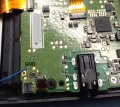
Hardware N3DS NAND backup possible, I hope.

gamesquest1

Nabnut
Former Staff
Joined
Sep 23, 2013
Messages
15,153
Trophies
2
XP
12,247
Yeah I kinda got that part. Thankfully, If I was reasonably gentle when I opened them. If I press on them while the system is on with my finger they both work. Wonder what are my options now... Glue ?
not glue, you would probably just coat the contacts, try wedging a very small piece of card/thin plastic (like screen protector thickness with 1 or 2 layers) in with the connector if its now too loose to properly grip the cables

but first thing to try would be trying to press down hard enough on them to get them back into place but not too hard as to damage them or bend/snap the pins inside
 

mvmiranda

Well-Known Member
Member
Joined
Oct 29, 2013
Messages
1,457
Trophies
1
Location
Brazil, Sao Paulo
Website
www.gamemod.com.br
XP
1,673
Country
Brazil
It didn't work :/

This is my "setup" (a little "accident" happened with the CMD wire so I had to "repair" it)

BIG pic inside!
24v39ea.jpg
I checked and there isn't any shorts between the wires... I don't know what's happening...
 

urherenow

Well-Known Member
Member
Joined
Mar 8, 2009
Messages
4,815
Trophies
2
Age
48
Location
Japan
XP
3,739
Country
United States
Well, got my TUC-300 in the mail today. It still doesn't work. Hardly ever even triggers the blue screen. I've now triple verified my wires with an ohm meter. All 0.0 except for gnd, which hovers between 0.1 and 0.2 when testing from the SD adapter to any internal shielding.

Are my wires TOO short? Is that even possible? When I do make it work, the error is still different:

00F800FE
00000000 00000000
00000003 00000000

Has anybody here used the alternate clk point and it works? Is it not possible that even though there is continuity between the 4 points on one side and the extra point on the other, the signal can be changed slightly? Just trying to figure this out, and figure out why there are 4 tiny points on the back... is it because multiple things are being driven by the same clk signal?

I tried wiring directly to the mSD pins on the TUC-300 and I'm still not able to get my PC to recognize it.

Wish I hadn't messed up my original N3DS... it was much less of a hastle than this one (different nand chips) :(
 

Avalynn

I'm here to learn and help.
OP
Member
Joined
Feb 23, 2014
Messages
407
Trophies
0
Age
36
Location
CA
XP
307
Country
United States
It didn't work :/

This is my "setup" (a little "accident" happened with the CMD wire so I had to "repair" it)

BIG pic inside!
24v39ea.jpg
I checked and there isn't any shorts between the wires... I don't know what's happening...

Are you getting the system to boot error every time? Once it's in boot error mode hookup disonnect it from the 3DS, plug it into the computer but without that red jumper there. Once the greyed out drive letter pops us, plug it back into the 3DS then re-install the jumper or press the contact closed manually. It's why I was suggesting a switch. ;)
Best of luck please keep us informed!

Well, got my TUC-300 in the mail today. It still doesn't work. Hardly ever even triggers the blue screen. I've now triple verified my wires with an ohm meter. All 0.0 except for gnd, which hovers between 0.1 and 0.2 when testing from the SD adapter to any internal shielding.

Are my wires TOO short? Is that even possible? When I do make it work, the error is still different:

00F800FE
00000000 00000000
00000003 00000000

Has anybody here used the alternate clk point and it works? Is it not possible that even though there is continuity between the 4 points on one side and the extra point on the other, the signal can be changed slightly? Just trying to figure this out, and figure out why there are 4 tiny points on the back... is it because multiple things are being driven by the same clk signal?

I tried wiring directly to the mSD pins on the TUC-300 and I'm still not able to get my PC to recognize it.

Wish I hadn't messed up my original N3DS... it was much less of a hastle than this one (different nand chips) :(
I have used the CLK signal on both sides of the board with success, and sometimes find the top test pad is actually easier to route at times.

The four pads on the back, based on their spacing and location, remind me of a SMD crystal oscillator footprint:
IM120917009.jpg


It should always go into boot error mode when the SD card reader is plugged into the 3DS but not the PC, you can simulate this your self by grounding CMD/CLK/DAT0. I've used that card reader many times myself but again I can't say if they have changed anything, I know other members have gotten it to work as well.
 
  • Like
Reactions: BerserkLeon

mvmiranda

Well-Known Member
Member
Joined
Oct 29, 2013
Messages
1,457
Trophies
1
Location
Brazil, Sao Paulo
Website
www.gamemod.com.br
XP
1,673
Country
Brazil
Are you getting the system to boot error every time? Once it's in boot error mode hookup disonnect it from the 3DS, plug it into the computer but without that red jumper there. Once the greyed out drive letter pops us, plug it back into the 3DS then re-install the jumper or press the contact closed manually. It's why I was suggesting a switch. ;)
Best of luck please keep us informed!
...

I get what you mean...

Yeah! I get the boot error code everytime... The errorcode looks funky though... something like this 000003 000000, but I get it everytime.
Will try that once I get home :)

Also, I will redo all of my soldering. Will remove that solder connection between the CMD wire (to reduce noise?) and will shorten the wires a bit more (I think I have room for that).

BTW, this N3DS mod is a pain in the back lower part, right?! The O3DSes were so easy to mod...
 

Avalynn

I'm here to learn and help.
OP
Member
Joined
Feb 23, 2014
Messages
407
Trophies
0
Age
36
Location
CA
XP
307
Country
United States
I get what you mean...
Will try that once I get home :)

Also, I will redo all of my soldering. Will remove that solder connection between the CMD wire (to reduce noise?) and will shorten the wires a bit more (I think I have room for that).

BTW, this N3DS mod is a pain in the back lower part, right?! The O3DSes were so easy to mod...
Haha actually I like the N3DS XL compared to the O3DS that was a little more trickier with the CLK point, but the 3DS XL now that was a charm right? ;)
 

urherenow

Well-Known Member
Member
Joined
Mar 8, 2009
Messages
4,815
Trophies
2
Age
48
Location
Japan
XP
3,739
Country
United States
I'm convinced. My wires are too small. Single core awg30 just isn't working. Got in the Anker reader today and it doesn't work either. I just stripped an old broken cable down to individual wires and will use it instead (awg 26, I think, twisted, not single core).
 

urherenow

Well-Known Member
Member
Joined
Mar 8, 2009
Messages
4,815
Trophies
2
Age
48
Location
Japan
XP
3,739
Country
United States
I need a hammer. Just re-soldered everything. same results. Now on the TUC-300 I have

00FBDDEF
FFFFFFFF FFFFFFFF
00000007 00800000

I know... I should have taken pictures this time. But I didn't. And I'm really tired of taking this thing apart... although it's working the first time every time now (vice having to put all of the cables on twice)

This time, I'm still using ground from the power connector and the CLK on that same side, but DAT0 and CMD are routed the long way around this time. Seems less likely to break this way anyhow.
 

urherenow

Well-Known Member
Member
Joined
Mar 8, 2009
Messages
4,815
Trophies
2
Age
48
Location
Japan
XP
3,739
Country
United States
I would suggest moving the GND point. Not sure why, but I've had problems with GND points on or near the charge connector.
Son of a BI%&!!!

How? I can't even...

I moved the ground and the damn thing works. With most of my readers. Where I had it before had continuity with the shielding (Everywhere... mSD slot, whatever the big cover is...). The new spot has continuity with the same stuff (used the pad just above the square one on the lower left of the board). How on earth does it make a difference? Please, somebody tell me! How much work I've put into troubleshooting this damn thing. How many times re-soldering (and today swapping out the wires). Two more memory card readers purchased (one of which I may have trashed... at least the mSD slot in it anyway.

Anyway, thank you so much!
 
  • Like
Reactions: mvmiranda

mvmiranda

Well-Known Member
Member
Joined
Oct 29, 2013
Messages
1,457
Trophies
1
Location
Brazil, Sao Paulo
Website
www.gamemod.com.br
XP
1,673
Country
Brazil
That looks fine, hope it all works out for you!

It didn't work :/ I'm not sure if this reader will work for this project

All I did was, switch off the switcher, plug the reader to my N3DS XL and I get booterror blue screen. Then I removed it, plugged to my computer (no grayed out drive letter appear), plugged back to the N3DS and switched on the switcher. Nothing happens :/

EDIT: I could be related to what hundshamer said!
 

mvmiranda

Well-Known Member
Member
Joined
Oct 29, 2013
Messages
1,457
Trophies
1
Location
Brazil, Sao Paulo
Website
www.gamemod.com.br
XP
1,673
Country
Brazil
I would suggest moving the GND point. Not sure why, but I've had problems with GND points on or near the charge connector.
Hmmm, I'm using exactly this GND spot... Will it be the case?
Son of a BI%&!!!

How? I can't even...

I moved the ground and the damn thing works. With most of my readers. Where I had it before had continuity with the shielding (Everywhere... mSD slot, whatever the big cover is...). The new spot has continuity with the same stuff (used the pad just above the square one on the lower left of the board). How on earth does it make a difference? Please, somebody tell me! How much work I've put into troubleshooting this damn thing. How many times re-soldering (and today swapping out the wires). Two more memory card readers purchased (one of which I may have trashed... at least the mSD slot in it anyway.


Anyway, thank you so much!

N3DS normal or XL? What GND are you using?
 

urherenow

Well-Known Member
Member
Joined
Mar 8, 2009
Messages
4,815
Trophies
2
Age
48
Location
Japan
XP
3,739
Country
United States
Hmmm, I'm using exactly this GND spot... Will it be the case?

N3DS normal or XL? What GND are you using?
N3DS XL. I was using a ground post from the power connector. I moved it to the recommended spot in the pics on the first post. It works now. Don't ask me why. They get continuity to the same stuff...
 

Attachments

  • UsabeGND.jpg
    UsabeGND.jpg
    121.9 KB · Views: 460
  • Like
Reactions: mvmiranda

mvmiranda

Well-Known Member
Member
Joined
Oct 29, 2013
Messages
1,457
Trophies
1
Location
Brazil, Sao Paulo
Website
www.gamemod.com.br
XP
1,673
Country
Brazil
N3DS XL. I was using a ground post from the power connector. I moved it to the recommended spot in the pics on the first post. It works now. Don't ask me why. They get continuity to the same stuff...

Man, I'll be very pissed off (and happy at the same time, hehe) if this works for me :)
Trying it now...
 

Avalynn

I'm here to learn and help.
OP
Member
Joined
Feb 23, 2014
Messages
407
Trophies
0
Age
36
Location
CA
XP
307
Country
United States
I would suggest moving the GND point. Not sure why, but I've had problems with GND points on or near the charge connector.
Son of a BI%&!!!

How? I can't even...

I moved the ground and the damn thing works. With most of my readers. Where I had it before had continuity with the shielding (Everywhere... mSD slot, whatever the big cover is...). The new spot has continuity with the same stuff (used the pad just above the square one on the lower left of the board). How on earth does it make a difference? Please, somebody tell me! How much work I've put into troubleshooting this damn thing. How many times re-soldering (and today swapping out the wires). Two more memory card readers purchased (one of which I may have trashed... at least the mSD slot in it anyway.

Anyway, thank you so much!
N3DS XL. I was using a ground post from the power connector. I moved it to the recommended spot in the pics on the first post. It works now. Don't ask me why. They get continuity to the same stuff...

You can't use the ground near the power connector or on it unfortunately :wink:
If you check around it, it actually goes though an inductor, or transformer, but I am voting it's being used an inductor, before getting to the ground plane. That adds a little resistance to it and I don't think the inductor is charging since there is no power at the connector.

Inductors start off as a open circuit until their magnetic fields are charged and stabilized which then it acts as a short. The reason for the inductor is to help handle changes in current, since the wall supply is a switching supply the inductor here helps stabilize the switching noise from the charger.

P.S. if you have a good multimeter you can check the resistance of the inductor from other points on the GND plane and there should be a bit of difference.
 

Site & Scene News

Popular threads in this forum

General chit-chat
Help Users
  • No one is chatting at the moment.
    NinStar @ NinStar: :wub: