Hardware GBA Usb-c charging not working. Gba sp.

17617

Member
OP
Newcomer
Joined
Jun 6, 2022
Messages
6
Trophies
0
Age
22
Location
Alberta
XP
37
Country
Canada
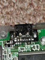
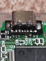
I sat with my gba sp in my back pocket with the charger in, then the charging stopped working. It worked when I pressed down on it but I then got it resoldered now it doesn't charge at all even when I press it down it doesn't work. Should I replace the usb-c charging port entirely or any suggestions?
 

Attachments

  • 16558573956663132084159324960579.jpg
    16558573956663132084159324960579.jpg
    1 MB · Views: 91
  • 1655857471701453286330190817285.jpg
    1655857471701453286330190817285.jpg
    1,009.2 KB · Views: 76

FAST6191

Techromancer
Editorial Team
Joined
Nov 21, 2005
Messages
36,798
Trophies
3
XP
28,321
Country
United Kingdom
If it worked pushing it before replacement that probably rules out most problems with any other component (fuses, inductors and such).

The images are not the clearest (not that super high res necessarily tells me much when it comes to subtle breaks in traces) and I am not sure what you connected to what right now either or if that board is supposed to be a drop in replacement (getting 5V out of USB-C looks to be annoying https://pinoutguide.com/Slots/usb-type-c_pinout.shtml https://microchipdeveloper.com/usb:tc-pins#toc2 compared to regular USB).

If it is a shearing action or bend from being sat on then I would worry about broken traces, and that is not even considering what might have been done to remove the remains of the broken original socket. At this point if you can't immediately spot any kind of broken trace I would probably take the jumper wires that go down onto the board and wire them directly into something a bit further into the PCB -- some kind of nice via, test pad, leg of chip (or chips if it splits) and seeing if that does something, then work backwards to find where the break might be (or not if you are happy with it at that point).
 

17617

Member
OP
Newcomer
Joined
Jun 6, 2022
Messages
6
Trophies
0
Age
22
Location
Alberta
XP
37
Country
Canada
So go further into where the pad go and remove some of the top layer and try to resolder it? Should I use a new component I wanna use usb c charing and audio mod So I would have to remove the old component and do what I said before? Like remove some of the top layer further down the pads the resolder the new component in?
 

FAST6191

Techromancer
Editorial Team
Joined
Nov 21, 2005
Messages
36,798
Trophies
3
XP
28,321
Country
United Kingdom
You can scrape some of the trace off if you want but there is usually going to be something easier to solder to if you go further into the circuit. That said yeah go away from where any fractures in the trace might be (the force does not end with the connector, indeed some would say count yourself lucky it did not snap a part of the PCB off)

I am not sure what you mean by audio mod. Is there an existing setup? USB-C it seems can do raw audio (either the D pins or possibly sideband) so I guess you are trying to wire up the SP's audio out into that as well ( http://problemkaputt.de/gbatek.htm#auxsoundheadphonesocketandbatterypowersupply , not sure what you want to do to ground the pin out in case of USB-C connected to disable the speaker*. Or do you mean you want to try one of the loudness mods (I think there is one for the SP** but can't remember where I saw things)


*main choices being permanent disable the onboard speaker, switch somewhere, dongle on the USB-C (maybe you have an adapter to go to 3.5mm, maybe even has some kind of switch inside the thing -- most 3.5mm sockets have something like this built in, indeed it failing is often why phones and such thing headphones are plugged in when they are not) or custom USB-C cable/cable from your headphones.

**owing to various regs in countries they often limit the max audio output volume onboard devices, tweaking it then being as simple as replacing a resistor in some cases. https://gbatemp.net/threads/hardwar...volume-of-your-3ds-some-models-so-far.400221/ for the 3ds equivalent.
 

FAST6191

Techromancer
Editorial Team
Joined
Nov 21, 2005
Messages
36,798
Trophies
3
XP
28,321
Country
United Kingdom
Seems I am behind on my GBA part replacement oddities as well as USB-C nitty gritty https://www.electronicdesign.com/industrial-automation/article/21808528/11-myths-about-usb-typec

Anyway link for others playing along at home
https://retrogamerepairshop.com/col...mod-with-audio-support?variant=40026783219884
Video they link at the bottom

Installation guide
https://giltesa.com/en/2021/06/08/game-boy-advance-sp-usb-c-and-audio-kit

Appears to be a plated down the side thing we used to see on mod chips that goes to the pads.

Seeing the video and how easy it appears to be to lift the pads then I would have to question the pad above C56 in yours (though it could just as easily be camera/light angle)

Looking at http://problemkaputt.de/gbatek.htm#auxsoundheadphonesocketandbatterypowersupply and some PCB shots then test pads (which would hopefully have dodged any lifting and thus also be good candidates for the jumper wires to go to for testing) are given as well.
If it is the same numbers as in gbatek (and I would imagine it is) then said dodgy looking pin (pin 2) is the voltage in pin in this case. Your jumper would then want to go to P32 on the back of the board but it is all the way on the other side (maybe you can slide it past the hole in the middle) and there might be better candidates nearer on some of the vias.

Equally if you can do jumper wires then you could probably add your own audio out to the existing USB-C port you have there without dropping another $27 plus whatever tax and shipping. Some discussion of the methods available on the link and the video, though I am not sure what the switch connected to disable the speaker setup is going to look like.
 

Site & Scene News

Popular threads in this forum

General chit-chat
Help Users
  • No one is chatting at the moment.
    SylverReZ @ SylverReZ: https://www.youtube.com/watch?v=TKyNPg7UIIc