


HI everybody
I Tried 3 time to make the hardmod picofly on switch butttt... i've got 3 time the same problem (with LED indication), This one : *== No eMMC CMD1 request (poor wiring, or dead CPU)
Can you help me because i don't understand my problem...
Let's make a resume of the situation :
The components :
-I use this Wire ( not Kynar wire maybe it's the problem ?) : 38AWG for the CLK point, 32AWG for the 3.3v, and 36AWG for the other points (GND, Dat0, CMD, RST, CPU)
-RPZero : i made a full install software in first step with v2.73 fimrware uf2
-I use 47 R resistances and and I checked with the multimeter if the 3 resistances was indeed 47 ohm. So this it's Ok
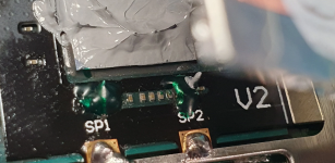
- For the 2 First Switch i used this Mofsets but for the last one i use Adaptator V2 like this one :

- I use this Dat0 adpatator
Now we can pass to the soldering points :
So we got 7 points of soldering
-GND :
 the GND is perfectly soldered
-3.3v :
 the 3.3v is perfectly soldered
- The Dat0 :

 for this i use the multimeter in diode mode to get this value (between 0.5 and 0.8), what do you think about that ?
-CMD :

There is a thing to use the multimeter and check that is ok ?
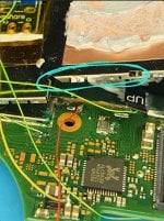
- CLK :
 it was a tricky one but soldering is done.
There is a way to check with the multimeter if it's ok ?
- RST :
 the RST is perfectly soldered
- CPU :

This was a hard port because of the tiny soldering but i made a very good soldering so ...
there is a way to check that with multimeter
So the CMD and the CLK or the CPU need to be check maybe with multimeter if you have any tips ?
I hope you can find any solutions to this problem, the CPU is dead or anything with this LED Patern ?
any help will be appreciated")
thank you
I Tried 3 time to make the hardmod picofly on switch butttt... i've got 3 time the same problem (with LED indication), This one : *== No eMMC CMD1 request (poor wiring, or dead CPU)
Can you help me because i don't understand my problem...
Let's make a resume of the situation :
The components :
-I use this Wire ( not Kynar wire maybe it's the problem ?) : 38AWG for the CLK point, 32AWG for the 3.3v, and 36AWG for the other points (GND, Dat0, CMD, RST, CPU)
-RPZero : i made a full install software in first step with v2.73 fimrware uf2
-I use 47 R resistances and and I checked with the multimeter if the 3 resistances was indeed 47 ohm. So this it's Ok
- For the 2 First Switch i used this Mofsets but for the last one i use Adaptator V2 like this one :
- I use this Dat0 adpatator
Now we can pass to the soldering points :
So we got 7 points of soldering
-GND :
-3.3v :
- The Dat0 :
-CMD :
There is a thing to use the multimeter and check that is ok ?
- CLK :
There is a way to check with the multimeter if it's ok ?
- RST :
- CPU :
This was a hard port because of the tiny soldering but i made a very good soldering so ...
there is a way to check that with multimeter
So the CMD and the CLK or the CPU need to be check maybe with multimeter if you have any tips ?
I hope you can find any solutions to this problem, the CPU is dead or anything with this LED Patern ?
any help will be appreciated
thank you


 Or others
  . Saves on time, soap, water and money having to wash them.