Please measure the individual points in diode mode. And a few pictures are always very helpful")
Post automatically merged:
Measure data point 0 with the multimeter and check the values
Please measure the individual points in diode mode. And a few pictures are always very helpful
Measure data point 0 with the multimeter and check the values
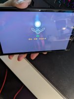
I had this error once. It's something usually associated with a bad connection between the modchip and the dat0 line. Those Hwfly chips make it harder to diagnose because the issue can be between the ribbon ZIF connectors or the ribbons on the board. Or even just a bad board altogether. Check every area between modchip and dat0 point to ensure there is no flux or residue or cold solder joints. If you used dat0 adapter under EMMC it could also be poor connection there.Hello, I'm trying to mod my oled switch, I finished the mod and I'm getting this error *==, then the switch boots into OFW and everything is working fine.
Where do I start on troubleshooting this?
. Watch the video and check the boot times with this configuration.Thank you for your replyPlease measure the individual points in diode mode. And a few pictures are always very helpful
. It's a messy job I know. See my message with the diode measurements.I had this error once. It's something usually associated with a bad connection between the modchip and the dat0 line. Those Hwfly chips make it harder to diagnose because the issue can be between the ribbon ZIF connectors or the ribbons on the board. Or even just a bad board altogether. Check every area between modchip and dat0 point to ensure there is no flux or residue or cold solder joints. If you used dat0 adapter under EMMC it could also be poor connection there.
Added a video measuring CLK/point dThank you for your reply
I measured point C (Dat0) and getting 0.755 which is within range.
Point 3v3 is getting 1.030
Point A is getting 0.745
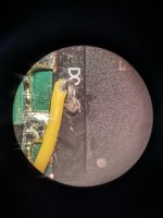
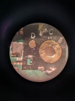
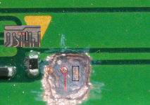
Point D(CLK) is getting zero on the modchip, but on flex cable it's connecting on and off, directly at the soldering joint CLK it's getting about 0.645.
RST is getting ~ 1.8
I think CLK is the problem, it seems soldering correctly, especially since I'm measuring something when I measure at the solder point.
How do I go about fixing this?
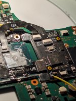
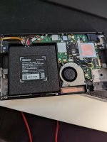
Attached some pictures
Post automatically merged:
See my message with the diode measurements.
I get 0.755 at the dat0 adapter, same thing at point C solder joint on flex cable and same thing at point C gold contact on modchip. That means Dat0/point C is good right?
In my post above, I found that CLK/point D isn't getting any readings on board, maybe that's the issue, not sure on how to go about fixing that
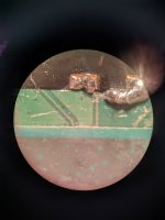
For a start the connection for the wire to the dat0 adapter is definitely a cold joint. Which can definitely prevent the chip from glitching. Also you should be using solid core wires and not stranded ones. The stranded wires can cause problems with the glitch also.Thank you for your reply
I measured point C (Dat0) and getting 0.755 which is within range.
Point 3v3 is getting 1.030
Point A is getting 0.745
Point D(CLK) is getting zero on the modchip, but on flex cable it's connecting on and off, directly at the soldering joint CLK it's getting about 0.645.
RST is getting ~ 1.8
I think CLK is the problem, it seems soldering correctly, especially since I'm measuring something when I measure at the solder point.
How do I go about fixing this?
Attached some pictures
Post automatically merged:
See my message with the diode measurements.
I get 0.755 at the dat0 adapter, same thing at point C solder joint on flex cable and same thing at point C gold contact on modchip. That means Dat0/point C is good right?
In my post above, I found that CLK/point D isn't getting any readings on board, maybe that's the issue, not sure on how to go about fixing that
Post automatically merged:
Added a video measuring CLK/point d
Thanks for the explanation. I'll reflow dat0 but for CLK, I had a thought, can I just run a wire from CLK to point d on modchip instead of soldering to flex cable? Just for the CLK, because I have a suspicion that the CLK links on the flex cable might be bad.For a start the connection for the wire to the dat0 adapter is definitely a cold joint. Which can definitely prevent the chip from glitching. Also you should be using solid core wires and not stranded ones. The stranded wires can cause problems with the glitch also.
You could be getting a measurement from the CLK point on the flex because the act of measuring the point applies pressure and makes the connection temporarily. I don't like those flex cables because you can't really see whats going on under them but I would definitely reflow the joint on the dat0 adapter with some flux and same for the CLK point, while applying some light pressure to the flex to make sure it is not going to break the connection as soon as you remove the iron.
Seems there is more than one problem area so start with those, test it out and go from there.
The stranded wires can cause problems with the glitch also.

People don't seem to know the difference between them. ALWAYS use solid core for small points, and stranded for larger.You should be using solid core wires and not stranded ones. The stranded wires can cause problems with the glitch also.

I have a suspicion that the CLK links on the flex cable might be bad.
Ok, I've refried the CLK and Dat0 points and I detect something in all the pins. Now when I turn on switch, the modchip flashing blue, and nothing is happening, it just keeps flashes blue. What does that mean?You can also make direct connections. That's what the individual points on the chip are for (A,B,C,D,3V3,GND).
Flex cables must not be soldered too hot.
Holy smoke! >.< you have to expose dat1 line, it will be difficult but you have to be careful. I suggest if you are doing kamikaze do it with a 0.2mm dremel tip. It is risky doing this job to be honest.i thing i kill my oled board. can someone help with D0 point

I'm able to boot into OFW with no issues so extra resistor was not neededCongratulations. Then I hope that you can also start the OFW properly. If not, you can solder a 100 ohm resistor to CMD & DAT0 each.
Or an additional 47 ohm resistance.
i was about to tell you that your Mosfet was on the up cpu shield and it needs to be under.I bet it was grounding anywhere. Happy that you already realize it .Ok, I've refried the CLK and Dat0 points and I detect something in all the pins. Now when I turn on switch, the modchip flashing blue, and nothing is happening, it just keeps flashes blue. What does that mean?
Post automatically merged:
I did it! The mosfet wasn't tucked under shield. Tucked under and I see picofly!! Thanks for the help everyone.
It took a couple of tries lol. I could glitch without the CPU shield but failed with shield on. That's when it hit me that mosfets were grounding.i was about to tell you that your Mosfet was on the up cpu shield and it needs to be under.I bet it was grounding anywhere. Happy that you already realize it .
I'm curious, what made you go kamakazi vs the dat0 adapter, dat0 adapter is much easier and safer
Dat1 via is gone ? At leat it looks like yes. All ready reply to you PM. You can bring your switch to me and maybe i can save it. I advise you not to do anything else. I live next to Parque das Nações .
Dont forget to isolate the cpu solder points with kapton tape. Clean all the area with IPA solution first.It took a couple of tries lol. I could glitch without the CPU shield but failed with shield on. That's when it hit me that mosfets were grounding.
It was surprisingly not as difficult to solder and mod as others made it out to be, just had to take my time and be careful. Having a microscope was the key, I didn't realize how tiny everything was from pics and videos
Post automatically merged:
I'm curious, what made you go kamakazi vs the dat0 adapter, dat0 adapter is much easier and safer