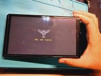
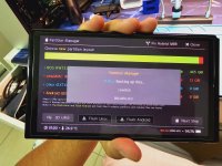
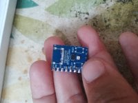
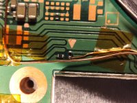
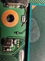
Not have raspberry icon because use sdloader of hwflyWhat firm flashed on RP2040? As far as I know, you must see the raspberry icon when starting without SD card.
You are using an out of date browser. It may not display this or other websites correctly.
You should upgrade or use an alternative browser.
You should upgrade or use an alternative browser.
Staff Posts
Recent threadmarks
sharing files
Important Posts
Recent threadmarks
FirmwaresIts still show rasp iconWhat firm flashed on RP2040? As far as I know, you must see the raspberry icon when starting without SD card.
Earlier i flash hekate sdloader so it looks like that
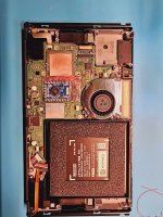
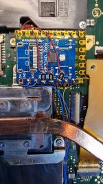
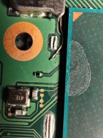
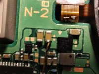
It fits perfect here (close to the speaker), just make sure everything is insulated because the shield goes very close to the edge of rp2040 on this position.What's the best location to put the standard RPI2040 on a switch lite?
I took this picture before covering everything in kapton so again, make sure you don't short something
Attachments
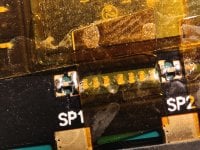
if you don't want to trim, it will fit but you have to cover it carefully and make sure it fit perfectly before you put the shield on. i no longer do that , recently i trim the chip a little bit and it fit perfectly.What's the best location to put the standard RPI2040 on a switch lite?
Attachments
I pulled off the foam and put a layer of kapton on top of the shieldThanks. Did you cut/pull off the foam that is on the shielded area beneath, or just compress it down?
I position it as sx lite, the same.What's the best location to put the standard RPI2040 on a switch lite?
Hello everyone, I have done many modchip installs on V2 and today I attempted to mod my oled.
I installed the chip, only thing I noticed is that RST diode value was ~1.3 but some people said it is normal for picofly.
Everything worked fine, chip worked, I booted into OFW to test the joycons and everything was okay. I turned off the console and started to reassemble. After reassembling I got black screen and a code on the chip, **, which means RST not connected.
It is now 4am and I have tried nearly everything, I reflashed the firmware (with nuke before flash), I redid the RST point and got the same 1.3 reading... no boot, same error.
I even tried disconnecting the chip by desoldering the 3.3V line and the console does nothing... no OFW just black screen. I do not understand what may have gone wrong, my soldering is very good, I even have pictures.
RST point without chip is 0L, I read somewhere that the point needs to be intact for the console to boot ofw... I don't exactly have my hopes up, since I tried with the RST point disconnected too...
I hope it's not totally dead, I don't even know how it died, this sucks... Any help is appreciated, thank you in advance guys.
Just remember if RST error, it might be because wrong voltage supplied to the picofly.Hello everyone, I have done many modchip installs on V2 and today I attempted to mod my oled.
I installed the chip, only thing I noticed is that RST diode value was ~1.3 but some people said it is normal for picofly.
Everything worked fine, chip worked, I booted into OFW to test the joycons and everything was okay. I turned off the console and started to reassemble. After reassembling I got black screen and a code on the chip, **, which means RST not connected.
It is now 4am and I have tried nearly everything, I reflashed the firmware (with nuke before flash), I redid the RST point and got the same 1.3 reading... no boot, same error.
I even tried disconnecting the chip by desoldering the 3.3V line and the console does nothing... no OFW just black screen. I do not understand what may have gone wrong, my soldering is very good, I even have pictures.
RST point without chip is 0L, I read somewhere that the point needs to be intact for the console to boot ofw... I don't exactly have my hopes up, since I tried with the RST point disconnected too...
I hope it's not totally dead, I don't even know how it died, this sucks... Any help is appreciated, thank you in advance guys.
Why?
Heres the explanation:
The first time picofly turns on, it check the RST voltage. Its should be around 1.8V +- 0.2.
If you use 4.2V from the battery rather the 3.3V from the regulator ic, then the measurement will be invalid, and showing the false alert.
Here, in the souce code, the firmware use 3.3V as the references.
https://github.com/rehius/usk/blob/6530fd9fe58980ea03d47905bad5e871b9439b7a/main.c#L49
Theres a scenario in the past, when someone use the 4.2V from the battery.
https://gbatemp.net/threads/picofly-a-hwfly-switch-modchip.622701/post-10185044
In your cases, since you said, its worked fine, before reassemble. I think you have source the 3.3V line correctly. But after you reassembled then it goes wrong. I strongly believe you short circuit something in there, maybe by accidentally. That lead to a drop of voltage on the 3.3V line in picofly, and lead to the false alarm of RST disconnected.
The problem is, that Short Circuit might broke other thing, which i hope not. You might try to use hdmi adapter to make sure. Maybe its the oled connector problem.
If you use flex to the emmc, you need to take it of too. Since that could also be the probable cause. The connection in there are not solid (no soldering).
Last edited by abal1000x,
Thanks for the reply. I searched the thread and saw the battery problem. I did not make the same mistake, I am using voltage from the correct place.Just remember if RST error, it might be because wrong voltage supplied to the picofly.
Why?
Heres the explanation:
The first time picofly turns on, it check the RST voltage. Its should be around 1.8V +- 0.2.
If you use 4.2V from the battery rather the 3.3V from the regulator ic, then the measurement will be invalid, and showing the false alert.
...
I checked all picofly connections and there is no short anywhere, all measured good before and after it stopped working.
Is 0L on switch RST (B) point (when disconnected) okay?
The only explanation I can give for the reassembly causing an issue is that my 3.3V jumper on that cap may have touched the metal shield that sits on top, shorting my 3.3V line straight to ground... sounds bad, if anything, I hope it only fried the regulator IC, Is there an easy way to test if that did in fact happen?
Also, I am using flex for the emmc but it measures ok, and it worked before reassembly so I doubt that is a problem...
This is really unlucky, I don't feel like I did anything wrong.
Last edited by bepaqui,
Thanks for the reply. I searched the thread and saw the battery problem. I did not make the same mistake, I am using voltage from the correct place.
I checked all picofly connections and there is no short anywhere, all measured good before and after it stopped working.
Is 0L on switch RST (B) point (when disconnected) okay?
The only explanation I can give for the reassembly causing an issue is that my 3.3V jumper on that cap may have touched the metal shield that sits on top, shorting my 3.3V line straight to ground... sounds bad, if anything, I hope it only fried the regulator IC, Is there an easy way to test if that did in fact happen?
Also, I am using flex for the emmc but it measures ok, and it worked before reassembly so I doubt that is a problem...
This is really unlucky, I don't feel like I did anything wrong.
Can test the capacitors around de IC, if some of them is short you must replace IC.
See this video around 1:58 min:
Assuming you haven't fried anything on the board, problems with your eMMC will prevent you from booting the system. Take out that flex first then use a cleaning agent under the chip, this will 75% revive your console.Thanks for the reply. I searched the thread and saw the battery problem. I did not make the same mistake, I am using voltage from the correct place.
I checked all picofly connections and there is no short anywhere, all measured good before and after it stopped working.
Is 0L on switch RST (B) point (when disconnected) okay?
The only explanation I can give for the reassembly causing an issue is that my 3.3V jumper on that cap may have touched the metal shield that sits on top, shorting my 3.3V line straight to ground... sounds bad, if anything, I hope it only fried the regulator IC, Is there an easy way to test if that did in fact happen?
Also, I am using flex for the emmc but it measures ok, and it worked before reassembly so I doubt that is a problem...
This is really unlucky, I don't feel like I did anything wrong.
I will try it, but why does it say RST not connected all of a sudden after having worked once?Assuming you haven't fried anything on the board, problems with your eMMC will prevent you from booting the system. Take out that flex first then use a cleaning agent under the chip, this will 75% revive your console.
Post automatically merged:
No shorts around m92, only left side of max chip which is normal according to many sources.Can test the capacitors around de IC, if some of them is short you must replace IC.
See this video around 1:58 min:
...
Post automatically merged:
Disconnected the wire from RST and DAT0 on the board (didn't remove adapter yet but measured), then disconnected every other wire from the modchip. Switch still does nothing, black screen. I am unable to find any shorts on the board...
Edit:
I removed the adapter and cleaned the area with ethanol, still black screen. Is it even worth buying a usb c power meter at this point... Some say putting in hwfly can revive it, is that true..? Man, this totally sucks, after so many modchip installs I decide to do my own switch and it just dies inexplicably.
Last edited by bepaqui,
it's time for providing some pictures of your installation and the training section video, friend.I will try it, but why does it say RST not connected all of a sudden after having worked once?
Post automatically merged:
No shorts around m92, only left side of max chip which is normal according to many sources.
Post automatically merged:
Disconnected the wire from RST and DAT0 on the board (didn't remove adapter yet but measured), then disconnected every other wire from the modchip. Switch still does nothing, black screen. I am unable to find any shorts on the board...
Edit:
I removed the adapter and cleaned the area with ethanol, still black screen. Is it even worth buying a usb c power meter at this point... Some say putting in hwfly can revive it, is that true..? Man, this totally sucks, after so many modchip installs I decide to do my own switch and it just dies inexplicably.
As I said I removed the emmc adapter, I only have pictures of CPU flex, 3.3V, A and D. B is disconnected and C is also disconnected. I have no training video but it totally worked the first time before reassembly. This is bizarre.
Post automatically merged:
I did try with all wires off the modchip, you mean I should disconnect all wires from the board too? Will that make a difference...?@bepaqui Last try, uninstall all chip connections and turn on
Post automatically merged:
Sorry I meant to also reply here.it's time for providing some pictures of your installation and the training section video, friend.
Attachments
Similar threads
- Replies
- 3
- Views
- 2K
- Replies
- 2
- Views
- 549
- Replies
- 42
- Views
- 6K
Site & Scene News
New Hot Discussed
-
-
29K views
Nintendo Switch firmware update 18.0.1 has been released
A new Nintendo Switch firmware update is here. System software version 18.0.1 has been released. This update offers the typical stability features as all other... -
23K views
Nintendo officially confirms Switch successor console, announces Nintendo Direct for next month
While rumors had been floating about rampantly as to the future plans of Nintendo, the President of the company, Shuntaro Furukawa, made a brief statement confirming... -
23K views
New static recompiler tool N64Recomp aims to seamlessly modernize N64 games
As each year passes, retro games become harder and harder to play, as the physical media begins to fall apart and becomes more difficult and expensive to obtain. The... -
22K views
TheFloW releases new PPPwn kernel exploit for PS4, works on firmware 11.00
TheFlow has done it again--a new kernel exploit has been released for PlayStation 4 consoles. This latest exploit is called PPPwn, and works on PlayStation 4 systems... -
20K views
Nintendo takes down Gmod content from Steam's Workshop
Nintendo might just as well be a law firm more than a videogame company at this point in time, since they have yet again issued their now almost trademarked usual...by ShadowOne333 129 -
16K views
Name the Switch successor: what should Nintendo call its new console?
Nintendo has officially announced that a successor to the beloved Switch console is on the horizon. As we eagerly anticipate what innovations this new device will... -
16K views
A prototype of the original "The Legend of Zelda" for NES has been found and preserved
Another video game prototype has been found and preserved, and this time, it's none other than the game that spawned an entire franchise beloved by many, the very...by ShadowOne333 32 -
15K views
Anbernic reveals specs details of pocket-sized RG28XX retro handheld
Anbernic is back with yet another retro handheld device. The upcoming RG28XX is another console sporting the quad-core H700 chip of the company's recent RG35XX 2024... -
12K views
DOOM has been ported to the retro game console in Persona 5 Royal
DOOM is well-known for being ported to basically every device with some kind of input, and that list now includes the old retro game console in Persona 5 Royal... -
12K views
Nintendo Switch Online adds two more Nintendo 64 titles to its classic library
Two classic titles join the Nintendo Switch Online Expansion Pack game lineup. Available starting April 24th will be the motorcycle racing game Extreme G and another...
-
-
-
264 replies
Name the Switch successor: what should Nintendo call its new console?
Nintendo has officially announced that a successor to the beloved Switch console is on the horizon. As we eagerly anticipate what innovations this new device will...by Costello -
231 replies
Nintendo officially confirms Switch successor console, announces Nintendo Direct for next month
While rumors had been floating about rampantly as to the future plans of Nintendo, the President of the company, Shuntaro Furukawa, made a brief statement confirming...by Chary -
129 replies
Nintendo takes down Gmod content from Steam's Workshop
Nintendo might just as well be a law firm more than a videogame company at this point in time, since they have yet again issued their now almost trademarked usual...by ShadowOne333 -
121 replies
New static recompiler tool N64Recomp aims to seamlessly modernize N64 games
As each year passes, retro games become harder and harder to play, as the physical media begins to fall apart and becomes more difficult and expensive to obtain. The...by Chary -
82 replies
Nintendo Switch firmware update 18.0.1 has been released
A new Nintendo Switch firmware update is here. System software version 18.0.1 has been released. This update offers the typical stability features as all other...by Chary -
82 replies
Ubisoft reveals 'Assassin's Creed Shadows' which is set to launch later this year
Ubisoft has today officially revealed the next installment in the Assassin's Creed franchise: Assassin's Creed Shadows. This entry is set in late Sengoku-era Japan...by Prans -
81 replies
TheFloW releases new PPPwn kernel exploit for PS4, works on firmware 11.00
TheFlow has done it again--a new kernel exploit has been released for PlayStation 4 consoles. This latest exploit is called PPPwn, and works on PlayStation 4 systems...by Chary -
78 replies
"Nintendo World Championships: NES Edition", a new NES Remix-like game, launching July 18th
After rumour got out about an upcoming NES Edition release for the famed Nintendo World Championships, Nintendo has officially unveiled the new game, titled "Nintendo...by ShadowOne333 -
71 replies
DOOM has been ported to the retro game console in Persona 5 Royal
DOOM is well-known for being ported to basically every device with some kind of input, and that list now includes the old retro game console in Persona 5 Royal...by relauby -
65 replies
Microsoft is closing down several gaming studios, including Tango Gameworks and Arkane Austin
The number of layoffs and cuts in the videogame industry sadly continue to grow, with the latest huge layoffs coming from Microsoft, due to what MIcrosoft calls a...by ShadowOne333
-
Popular threads in this forum
General chit-chat
-
-
-
-
 @
Sonic Angel Knight:
@Psionic Roshambo off to naughty roleplay with ai chat? Just do it with vr chat instead.+3
@
Sonic Angel Knight:
@Psionic Roshambo off to naughty roleplay with ai chat? Just do it with vr chat instead.+3 -
-
 @
Xdqwerty:
@SylverReZ,
@
Xdqwerty:
@SylverReZ,
For my birthday I will go to the movies and then we will go to a restaurant where they serve pizzas and other things like ice cream for example. -
-
-
-
-
-
-
-
-
-
-
-
-
-
 @
Psionic Roshambo:
It's like Mario 64 if Mario was retarded and brain damaged and hit by a garbage truck!+2
 -
-
-
-
-


