Hacking Hardware Picofly - a HWFLY switch modchip

MusicCanKill

Member
Newcomer
Joined
Oct 6, 2020
Messages
23
Trophies
0
Age
34
XP
188
Country
Greece
So here's another confusing layer to all this- some Pico have a different LED, which has the pin for red and green opposite of the others. Some consoles fail green, some fail red. If someone has one that fails but is green, or succeeds but is red, then they need to solder the "RGB/GRB" jumper on the backside of their RP2040.
Yes ,exactly what i m saying but probably didn't explain best as english is not my native language.Sorry for that.
So only if somebody has one that actually gets into Hekate can be sure for the led color and and only on his specific board as , as far as i know, there is no way to tell if the board has the RGB or GRB led..
Then he has to find a console that the same pico board doesn't work on it (black screen) and check if the led color still goes to green or not..
Or if he is has the tools , make a logic analyzer log of the led commands sent from the mcu so the actual led will be irrelevant.
Maybe a simple fw turning the led green constantly should be made for people to distinguish if they have the RGB or GRB led model?
 

TheSynthax

Well-Known Member
Member
Joined
Apr 29, 2018
Messages
220
Trophies
0
XP
509
Country
United States
Yes ,exactly what i m saying but probably didn't explain best as english is not my native language.Sorry for that.
So only if somebody has one that actually gets into Hekate can be sure for the led color and and only on his specific board as , as far as i know, there is no way to tell if the board has the RGB or GRB led..
Then he has to find a console that the same pico board doesn't work on it (black screen) and check if the led color still goes to green or not..
Or if he is has the tools , make a logic analyzer log of the led commands sent from the mcu so the actual led will be irrelevant.
Maybe a simple fw turning the led green constantly should be made for people to distinguish if they have the RGB or GRB led model?
It's simple enough to tell. If yours fails to boot, but it's still green, then you need the jumper.
 

MusicCanKill

Member
Newcomer
Joined
Oct 6, 2020
Messages
23
Trophies
0
Age
34
XP
188
Country
Greece
It's simple enough to tell. If yours fails to boot, but it's still green, then you need the jumper.
I guess you have confirmed that ,right?
Cause there is still a chance that it really goes green but nothing happens.
I have had that happen on a friend with original sx chip and latest HW firmware.
Was trying to figure out what was happening for about an hour till i told him to revert to spacecraft which resolved the issue (yes i had deleted all configs and rewritten emmc , even cleaned and let it do the retraining..The glitch reported success on the serial console but nothing was happening on the actual console (no hekate/nosd)
In that case it would think it succeeded and that is why it would go green but in reality it has failed and should have been red..
 

Bekir57

Member
Newcomer
Joined
Feb 25, 2023
Messages
11
Trophies
0
Age
24
XP
39
Country
Turkey
Friends, the pins of the irs8342 I bought were broken, I'm thinking of buying a new one, but before I buy it, I wonder if I could use a larger mosfet, I would be happy if you suggest a model.
 

Attachments

  • 5DD175E1-5C74-4498-8860-1E148D0137DA.jpeg
    5DD175E1-5C74-4498-8860-1E148D0137DA.jpeg
    147.5 KB · Views: 66

Mansi

Well-Known Member
Newcomer
Joined
Jan 14, 2023
Messages
70
Trophies
0
Age
30
XP
331
Country
Belarus
Friends, the pins of the irs8342 I bought were broken, I'm thinking of buying a new one, but before I buy it, I wonder if I could use a larger mosfet, I would be happy if you suggest a model.
You can also use a large one. The main thing is that the parameters are approximately the same so that it switches quickly.
 
  • Like
Reactions: ifgfgfgfgfgfg

Bekir57

Member
Newcomer
Joined
Feb 25, 2023
Messages
11
Trophies
0
Age
24
XP
39
Country
Turkey
Bu kurtarılabilir görünüyor, çipteki uzun pedi kullanamaz mısın?
Unfortunately, I can't use it, the only g pin is broken and does not hold solder.

I have 1 more question, is the voltage value and amperage matching enough, so I should buy a 30v 8.8a mosfet and can you recommend me a sample mosfet?
 
Last edited by Bekir57,
  • Like
Reactions: ifgfgfgfgfgfg

throwaway_2387298724

New Member
Newbie
Joined
Feb 28, 2023
Messages
1
Trophies
0
Age
26
XP
15
Country
Bahrain
Hello :grog:, long time lurker here. I never done reverse engineering before so i decided to try, I have been looking at the unlocked firmware for the past 2 day and I am getting the hang of it, maybe i will post some more informations if i can get to a succesfull point i which i can deobfuscate the bct and other data.

For now i just wanted to share that the firmware read the bootrom version from the rp2040 and actually do some different preparation based on it, it seems it does not know about the new bootrom versions greater than 1.
That could be the cause of why the rp2040 work for a only few people.
 

Mansi

Well-Known Member
Newcomer
Joined
Jan 14, 2023
Messages
70
Trophies
0
Age
30
XP
331
Country
Belarus
I want to try to flash rp2040 with a non-working firmware and read the dump as 25 spi. Then compare them.
Most likely part of the memory is used for the loader and part for the executable code of the glitch. It's a theory)
 

ifgfgfgfgfgfg

Member
Newcomer
Joined
Dec 14, 2018
Messages
14
Trophies
0
Age
25
XP
157
Country
United Kingdom
Unfortunately, I can't use it, the only g pin is broken and does not hold solder.

I have 1 more question, is the voltage value and amperage matching enough, so I should buy a 30v 8.8a mosfet and can you recommend me a sample mosfet?
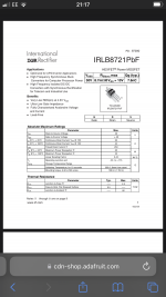
Try this irl 8721
 

Attachments

  • 86B65DD8-F112-429A-B3DE-6A9552070BCF.png
    86B65DD8-F112-429A-B3DE-6A9552070BCF.png
    501.4 KB · Views: 76

Mansi

Well-Known Member
Newcomer
Joined
Jan 14, 2023
Messages
70
Trophies
0
Age
30
XP
331
Country
Belarus
Time to find a new switch lite XD
the old one died?)
Post automatically merged:

RP2040 have a Winbond W25Q16 series
Code:
SPI ID EF4015 (EF40150000000000:9F:SFDP)
SPI Registers reading...OK
SPI Info Winbond W25Q16JV, size 2 MiB, 3.30V, clocks 25/50/50/50 MHz (SFDP)
Manufacturer Winbond
Model name W25Q16JV
Voltage 3.30V
CMD clocks 25/50/50/50 MHz (Slow/Fast/Dual/Quad)
SPI Status Register #1 0x00
SPI Status Register #2 0x02 (QE)
SPI Status Register #3 0x60 (DRV0 DRV1)
SPI UID E6611CB71F7B8129
SPI Security Registers 768 Bytes
Page size 0x100 (256)
Sector size 0x1000 (4 KiB)
Chip size 0x200000 (2 MiB)
im write ubuntu firmware and dump windbond...
first 11EE0 compared by 1 in 1.
And next code have differents...

left - dump, right - bin file
Post automatically merged:

Hmmm.... maybe work)
I write picofly firmware and only included rp2040 and have signs of a glitch
 

Attachments

  • 1.png
    1.png
    266.5 KB · Views: 60
Last edited by Mansi,

Adran_Marit

Walküre's Hacker
Member
Joined
Oct 3, 2015
Messages
3,781
Trophies
1
Location
42*South
XP
4,565
Country
Australia
the old one died?)
Post automatically merged:

RP2040 have a Winbond W25Q16 series
Code:
SPI ID EF4015 (EF40150000000000:9F:SFDP)
SPI Registers reading...OK
SPI Info Winbond W25Q16JV, size 2 MiB, 3.30V, clocks 25/50/50/50 MHz (SFDP)
Manufacturer Winbond
Model name W25Q16JV
Voltage 3.30V
CMD clocks 25/50/50/50 MHz (Slow/Fast/Dual/Quad)
SPI Status Register #1 0x00
SPI Status Register #2 0x02 (QE)
SPI Status Register #3 0x60 (DRV0 DRV1)
SPI UID E6611CB71F7B8129
SPI Security Registers 768 Bytes
Page size 0x100 (256)
Sector size 0x1000 (4 KiB)
Chip size 0x200000 (2 MiB)
im write ubuntu firmware and dump windbond...
first 11EE0 compared by 1 in 1.
And next code have differents...

left - dump, right - bin file
Post automatically merged:

Hmmm.... maybe work)
Im write dump from picofly and turn rp2040 only and have indications for glitch
Yeah I killed it ny accident. Stuck in rcm as I damaged a emmc line pad
 

flynnsmt4

Member
Newcomer
Joined
Feb 20, 2023
Messages
11
Trophies
0
XP
155
Country
United States
Hello :grog:, long time lurker here. I never done reverse engineering before so i decided to try, I have been looking at the unlocked firmware for the past 2 day and I am getting the hang of it, maybe i will post some more informations if i can get to a succesfull point i which i can deobfuscate the bct and other data.

For now i just wanted to share that the firmware read the bootrom version from the rp2040 and actually do some different preparation based on it, it seems it does not know about the new bootrom versions greater than 1.
That could be the cause of why the rp2040 work for a only few people.
From my limited reversal of this firmware you're probably looking at pico SDK runtime init routines which initialize fplib function pointers; different bootrom versions have differing levels of support for them, like double-precision floating point funcs.

I'd recommend compiling your own pico SDK binaries and comparing the two with symbols loaded to help orient yourself, or at least know when a function has an equivalent C version you can just look up to be a bit faster. One thing that quickly becomes apparent is that the entrypoint is copied to SRAM, specifically starting at ROM address 0x10013ABC and into SRAM addresses 0x200200C0 to 0x200212A0. In IDA I'd recommend just copying the firmware.bin contents to that address.

On the subject, I haven't really found anything interesting:

-The PIO assembly someone posted from earlier is just the ws2812 LED example from the rpi pico-examples repo which it uses to change the colour of the ws2812 LED: (cant post link)

-Speaking of the pico SDK, the initial VTOR that does BKPT 0 on every interrupt is copied into SRAM and patched to jump to whatever IRQ handler is required.. this is in every single pico SDK binary, although the entrypoint does weird stuff to the VTOR later like set it to 0xEE2F8D10 (an invalid address) which would probably make more sense if I followed the massive chain of STR instructions. They disable IRQ 3 (external?) beforehand so I assume it doesn't really use that value.

-They have a 1 second watchdog timeout, and if the watchdog triggers they set the LED colour to red(?) and reset the SOC.

-Before this it (I think) waits up to 300ms for a sequence on the CMD/gpio27 pin. It has a bunch of other logic involving the time since startup that would probably make more sense if I knew how the hwfly worked. It's here that it sets the LED colour to blue which represents "glitching".

-They do seem to be changing the clock speed to 333Mhz and setting the SOC voltage to 1.30 volts. I can't exactly tell what it's doing due to the abundance of divmod_u32u32 calls that I don't want to sift through.

-It also later exits the XIP flash, probably because they overwrite the ROM.

-It writes to SWD pins not just to prevent debugging but also to explicitly send commands. It does send a 35-byte sequence which I can't wrap my head around before it writes standard SWD commands to interact with debug/access port registers.
1677668873873.png


1677667465844.png

1677667487862.png

It then sends a series of more standard SWD commands. I see in later portions of the entrypoint it writes other SWD commands but I haven't had the chance to look at those yet:
1677667563863.png

In total, on each core,
-Write TARGETSEL (as seen above)
-Read DPIDR, discard value (in fact it doesn't seem to really care about any SWDO value)
-Write 0x1E to (debug) AP abort register
-Write 0x50000001 to CTRL/STAT register (debug)
-Write 0x10 to (debug) AP abort register
-Write 0x3 to (debug) AP select register
-Write 0xA2000012 to (Access port) CSW

For more info see the ADIv5.2 spec.

Most of this is intelligible but I can't figure out why the final access port write (presumably to the MEM-AP?) sets the prot bits to 0x44, and looking up coresight docs doesn't help much either. I assume this setup is so that they can do funny stuff like write to SRAM using the SWD protocol given that they use it a bit later. This function is called for both cores on core 0.
 

flynnsmt4

Member
Newcomer
Joined
Feb 20, 2023
Messages
11
Trophies
0
XP
155
Country
United States
why don't you want to continue?
Mostly because of stuff like this:
1677669626371.png

I'm sure it would make sense if I went through it line-by-line but doing that a thousand times starts to get a bit annoying ..

This is also a good candidate, how do I know without looking at that massive STR chain that it doesn't overwrite that magic constant it sets the VTOR to which isn't an actual address?
1677669774157.png
 

Site & Scene News

Popular threads in this forum

General chit-chat
Help Users
  • No one is chatting at the moment.
    BigOnYa @ BigOnYa: Wish they would let us play the NCAA football 14 on newer xbox, its one of the only games I love...