


nice case, really digging the redesign, do you plan to share the files?
I can, but beware that the big "GBS control" writing on the side isn't easy to print, it will likely come out deformed, this is how mine came out:
In order to correct the mistake, the guy that printed it made a plaque with the correct writing and applied it on top of it.
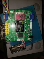
Also, not everything is perfect. For example, the video output cutout is still sized for the VGA port, so it's too small for the HDMI adapter, I had to manually cut a bigger hole in order to make it fit, the SCART cutout is too thin (although the width is fine) etc... This was the first time ever I edited an .stl file, so I'll post it with the understanding that you'll have to modify it yourself in order to make it functional (I called the file "unfinished draft" for this reason).
BTW, my intention is to put the power supply behind the SCART socket, a slim one should fit.
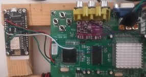
also on the last thing r26 resistor mod is used for component inputs as the brightness isn't quite up to snuff on them and may produce too dark an image. it is seperate from the one for SCART and should be off when SCART is in use as it would make the input from it too bright, only reason i added a switch was i plan on using both.
OK
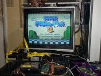
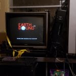
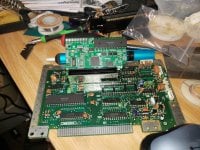
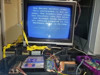
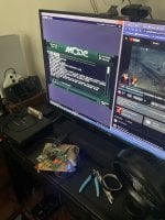
Yes, do it. That would be interesting.that all being said i ended up doing something completely diffrent with that board and am building another one now. currently using it to bring my nes tv back from the ghost using the gbsc and an arcade monitor board that worked with the tube i had in it. might post some pictures of that once it's all fininshed up.


 like a 250 dollar kit back when DDR4 was Intel only