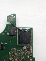
eMMC cover breaks dat0 connection

MrBabelPhish

Member
OP
Newcomer
Joined
Feb 6, 2024
Messages
8
Trophies
0
Age
25
XP
20
Country
United Kingdom
had a (self) modded switch with a Hwfly v5 chip for over a year now and has been working fine until last week, it ran out of battery and won't turn on. purple flashing then solid red.

I cracked it open and it seems the dat0 connection has given up, getting 1.5v on diode mode. However this is where things get weird.

If I check from the c point on the friction flex pcb, I get a clean 0.77ish V, so the contact there is still good, now if I solder a wire from that to the hwfly chip, and test the point on the chip to ground, 0.77-8V again. but as soon as I put the cover on the eMMC chip, it jumps up to 1.5V every time. I've re-soldered with different wire 3 times and practically mummified the thing in kapton tape and it still breaks the connection and gives 1.5V.

I've tried just testing the switch without the cover on and it gets the green light pretty quick.

Any ideas what it could be? it doesn't seem to be properly shorting to ground or anything? it's driving me crazy.
 

MrBabelPhish

Member
OP
Newcomer
Joined
Feb 6, 2024
Messages
8
Trophies
0
Age
25
XP
20
Country
United Kingdom

Attachments

  • PXL_20240206_133948776.jpg
    PXL_20240206_133948776.jpg
    2.1 MB · Views: 21

MichiS97

"Leftist snowflake milennial"
Member
Joined
Jun 14, 2011
Messages
1,815
Trophies
2
Age
26
Location
Munich
XP
3,600
Country
Germany
I don't know if it's the picture or not but your wire looks pretty thick or at least the insulation does.
What gauge is it? I'm just trying to rule out that the shield breaks through the insulation of the wire and causes a short.
 

MrBabelPhish

Member
OP
Newcomer
Joined
Feb 6, 2024
Messages
8
Trophies
0
Age
25
XP
20
Country
United Kingdom
I don't know if it's the picture or not but your wire looks pretty thick or at least the insulation does.
What gauge is it? I'm just trying to rule out that the shield breaks through the insulation of the wire and causes a short.
The wire is 30AWG, quite thick but not massively so. I did also think this, but I tried bending the corner of the shield up to avoid any pressure on the wire and it still happens.

plus then I Imagine it would short to the grounding of the shield, but it doesn't have continuity to ground, just the same exact 1.5v diode val
 

MichiS97

"Leftist snowflake milennial"
Member
Joined
Jun 14, 2011
Messages
1,815
Trophies
2
Age
26
Location
Munich
XP
3,600
Country
Germany
Ahhhh I may have an idea. I'm sorry but can you remove the DAT0 adapter again?
There are two test points below where the flex is which are connected tom GND. These test points are said to cause signal issues in some scenarios. Sthetix solves that by cutting the traces to those test points with a mini grinder. I usually just cover those points with liquid solder mask. Can you try doing that?
 

MrBabelPhish

Member
OP
Newcomer
Joined
Feb 6, 2024
Messages
8
Trophies
0
Age
25
XP
20
Country
United Kingdom
Ahhhh I may have an idea. I'm sorry but can you remove the DAT0 adapter again?
There are two test points below where the flex is which are connected tom GND. These test points are said to cause signal issues in some scenarios. Sthetix solves that by cutting the traces to those test points with a mini grinder. I usually just cover those points with liquid solder mask. Can you try doing that?
I'll give that a try and report back, though I don't have any solder mask on me, a bit of kapton should block it the same right?
 

MrBabelPhish

Member
OP
Newcomer
Joined
Feb 6, 2024
Messages
8
Trophies
0
Age
25
XP
20
Country
United Kingdom
yeah that should work, too. You can always cut the traces, too, if you have an x-acto knife or something like that
well I've done that, reattached the flexPCB and reconnected but I seem to still be struggling with the same problem.

After more experimenting It turns out 1.5V is actually also the reading between C and GND without anything connected, so it seems the 0.77V is being overridden with that, maybe my cable is a bit crap? intuitively C and GND shouldn't be connected? am I wrong?
 

MichiS97

"Leftist snowflake milennial"
Member
Joined
Jun 14, 2011
Messages
1,815
Trophies
2
Age
26
Location
Munich
XP
3,600
Country
Germany
Well do you have continuity between GND and C if you measure in continuity mode? If so then there is definitely something very wrong and that would confirm my assumption that you're shorting DAT0 to GND somehow
 

MrBabelPhish

Member
OP
Newcomer
Joined
Feb 6, 2024
Messages
8
Trophies
0
Age
25
XP
20
Country
United Kingdom
Well do you have continuity between GND and C if you measure in continuity mode? If so then there is definitely something very wrong and that would confirm my assumption that you're shorting DAT0 to GND somehow
Nope, no dodgy continuities anywhere.

I think it must be a cable issue, but I'm getting 0.77V when measuring from the C point on the flex PCB, but 1.5V when measuring on the matching C pad on the other end of the cable, but still somehow get continuity across the cable :wacko:
 

MichiS97

"Leftist snowflake milennial"
Member
Joined
Jun 14, 2011
Messages
1,815
Trophies
2
Age
26
Location
Munich
XP
3,600
Country
Germany
Nope, no dodgy continuities anywhere.

I think it must be a cable issue, but I'm getting 0.77V when measuring from the C point on the flex PCB, but 1.5V when measuring on the matching C pad on the other end of the cable, but still somehow get continuity across the cable :wacko:
In general I would strongly recommend not to use AWG30 wires for this mod. You might even get away with it for the DAT0 signal and the RST line, but for CLK and CMD I strongly advise against it.
I can recommend these wires (AliExpress), specifically the AWG36 ones. I think these are recommended by basically anybody who does these installs on a regular basis
 

MrBabelPhish

Member
OP
Newcomer
Joined
Feb 6, 2024
Messages
8
Trophies
0
Age
25
XP
20
Country
United Kingdom
In general I would strongly recommend not to use AWG30 wires for this mod. You might even get away with it for the DAT0 signal and the RST line, but for CLK and CMD I strongly advise against it.
I can recommend these wires (AliExpress), specifically the AWG36 ones. I think these are recommended by basically anybody who does these installs on a regular basis
Sweet, I've just ordered them, I can confirm its the wire, can't get a reliable connection with it to save my life
 

MichiS97

"Leftist snowflake milennial"
Member
Joined
Jun 14, 2011
Messages
1,815
Trophies
2
Age
26
Location
Munich
XP
3,600
Country
Germany
It's still weird, though. The choice of wire shouldn't matter that much for the DAT0 point as long as you're making a good connection.
Let me just verify a few things:
When you remove the wire from the DAT0 adapter and measure with the black probe on a GND point and the red probe on the C point on the flex, you get ~0,77V correct?
When you solder the wire to the C point on the modchip and then measure from the chip to a GND point, you also get 0,77 V but as soon as you put the heat shield over the eMMC back on, you measure 1,5V?
However, in none of these cases do you see continuity between GND and DAT0/C, correct?

Are you doing all of your measurements with the battery of the Switch disconnected?
 

MrBabelPhish

Member
OP
Newcomer
Joined
Feb 6, 2024
Messages
8
Trophies
0
Age
25
XP
20
Country
United Kingdom
It's still weird, though. The choice of wire shouldn't matter that much for the DAT0 point as long as you're making a good connection.
Let me just verify a few things:
When you remove the wire from the DAT0 adapter and measure with the black probe on a GND point and the red probe on the C point on the flex, you get ~0,77V correct?
When you solder the wire to the C point on the modchip and then measure from the chip to a GND point, you also get 0,77 V but as soon as you put the heat shield over the eMMC back on, you measure 1,5V?
However, in none of these cases do you see continuity between GND and DAT0/C, correct?

Are you doing all of your measurements with the battery of the Switch disconnected?
That is all correct, though I even struggle to get the C pad on the modchip to even read 0.77V consistently (without shield).

I'm getting no ground shorts at all, and the unit is completely disconnected from battery.

I've disconnected all other cables from the mod chip, and now the 1.5V is gone and its showing Open, but still struggling to get a good connection with the cable to maintain the 0.77V on the modchip end, my joints look pretty solid and I can reflow them and reflow them, but still poor connection.
 

Site & Scene News

Popular threads in this forum

General chit-chat
Help Users
  • No one is chatting at the moment.
    K3Nv2 @ K3Nv2: Lol rappers still promoting crypto