Dimensions for the GameCube memory card

SylverReZ

The planet is fine. The people are crazy.
OP
Member
GBAtemp Patron
Joined
Sep 13, 2022
Messages
7,233
Trophies
3
Location
The Wired
Website
m4x1mumrez87.neocities.org
XP
22,170
Country
United Kingdom

FAST6191

Techromancer
Editorial Team
Joined
Nov 21, 2005
Messages
36,798
Trophies
3
XP
28,348
Country
United Kingdom
Are there no gerber files and the like for GC2SD or the usb gecko any more?

I also saw the length at least vary with third party efforts.

I can possibly go find a GC and memory card when I get back this evening (naturally have verniers, callipers and all manner of other such toys. I would also ponder the other direction -- the main reason for wanting such a thing is to use an existing case (why in this era of 3d printing I don't know but simple enough request)
 

tech3475

Well-Known Member
Member
Joined
Jun 12, 2009
Messages
3,673
Trophies
2
XP
6,066
Country
I'd prefer it if I could get some reliable information regarding the dimensions.

Unfortunately this was the closest I can find, even looked around to see if someone had done a Gerber file and replacement cases (i.e. get the size based on the case).

I don’t recall if the gigaleak contained such information.
 
  • Like
Reactions: SylverReZ

FAST6191

Techromancer
Editorial Team
Joined
Nov 21, 2005
Messages
36,798
Trophies
3
XP
28,348
Country
United Kingdom
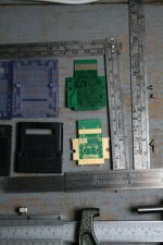
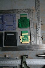
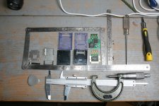
Turns out I had some time before I had to leave so had a bit of fun, can redo in higher res (thumbnails below so click for larger, forum sometimes crushes it a bit as well) and get a tripod/focus better for the back shots if needs be but should be enough.
For the official one then the micrometer reads in half mm (full rotation of the barrel is .50) so between the flats (ignoring the PCB breakaway rough bits) 28.5+.34 = 28.84mm (or actually halfway so you could imply further but there is possibly parallax and variation along by then as well as maybe compression), vernier was the long side so 35.58mm (.59 on the mic but again parallax and variation).PCB is 0.7mm on the Verniers. I am not putting it back together yet so high res or measuring the wings can be done if it needs to be. Inch lovers *spits* be careful on the vertical ruler on the right as part of it is whitworth pitch calculator/measurer and not plain inches.
IMG_2972.JPGIMG_2971.JPGIMG_2970.JPG
 
  • Like
Reactions: SylverReZ

SylverReZ

The planet is fine. The people are crazy.
OP
Member
GBAtemp Patron
Joined
Sep 13, 2022
Messages
7,233
Trophies
3
Location
The Wired
Website
m4x1mumrez87.neocities.org
XP
22,170
Country
United Kingdom
Turns out I had some time before I had to leave so had a bit of fun, can redo in higher res (thumbnails below so click for larger, forum sometimes crushes it a bit as well) and get a tripod/focus better for the back shots if needs be but should be enough.
For the official one then the micrometer reads in half mm (full rotation of the barrel is .50) so between the flats (ignoring the PCB breakaway rough bits) 28.5+.34 = 28.84mm (or actually halfway so you could imply further but there is possibly parallax and variation along by then as well as maybe compression), vernier was the long side so 35.58mm (.59 on the mic but again parallax and variation).PCB is 0.7mm on the Verniers. I am not putting it back together yet so high res or measuring the wings can be done if it needs to be. Inch lovers *spits* be careful on the vertical ruler on the right as part of it is whitworth pitch calculator/measurer and not plain inches.
View attachment 385019View attachment 385020View attachment 385021
Thank you very much FAST for the reply. :D
 

SylverReZ

The planet is fine. The people are crazy.
OP
Member
GBAtemp Patron
Joined
Sep 13, 2022
Messages
7,233
Trophies
3
Location
The Wired
Website
m4x1mumrez87.neocities.org
XP
22,170
Country
United Kingdom
Would have been able to help if I saw this sooner. Sounds like you're cooking something up. ;)
I'm working on a breakout board for the memory card port. Does anybody know the dimensions for the pins and also the distance between them (in mm ofc)? I'm working on a PCB footprint.
 
Last edited by SylverReZ,
  • Love
Reactions: AkikoKumagara

FAST6191

Techromancer
Editorial Team
Joined
Nov 21, 2005
Messages
36,798
Trophies
3
XP
28,348
Country
United Kingdom
You should be able to determine it from the image (there are fairly common pin pitches and trace widths which it probably conforms to). Are there really no copies of the SD gecko, USB gecko or something gerber files any more?
Shoved https://wiibrew.org/wiki/USB_Gecko in a gerber viewer and it gave me something I could probably use (inherently going to have some dimensions as it is a PCB schematic you send to a manufacturer).

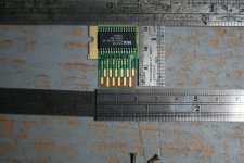
Anyway as my previous image was not necessarily the absolute easiest have another. That should be more than over target, rule(r)s aligned and in focus.
1690674348921.jpeg
There is nothing physical to register the verniers or mic on so would have use them/try to get it done optically (can't be bothered to get the microscope out at this time of night and I am too much of a failure to own a set of Jo blocks). With the verniers I think it might be 1mm width and measuring outside to outside of 2 pins on a row (several checks across the thing, as you would probably want to do if you made a pattern to see if it aligns as it would very quickly fall out of alignment/cumulative errors be fun. Alternatively use said cumulative to your advantage and measure across many as many pins as you can and divide down to lessen the error.) is 3.8mm maybe (3 lots of 1mm track and then the 0.8mm of gap split between the two or 1mm track and 1.8mm gap before another pin with vertically and horizontally staggered rows depending upon your philosophy). I will leave the vertical parts of the rows to your whims (most times longer ones are there for kiddies putting things in out of alignment so it meets ground first or gets power and ground to stop floating/capacitive voltages making odd signals for it.
Alternatively/for future ponderings it seems a few of those vias are centrally aligned on the trace and might make for a suitable reference point in this for measurement.
Re "in mm" I do have to note a lot of PCB work, especially at that time, would still have been conducted in imperial (even today you will hear "thou" in discussions of distances) so could be worth considering if any of the distances make more sense in that. Not to mention I doubt Nintendo made a custom thing for this and there is probably some socket type out there you could look at for this (2x6 row doing power, ground and a whole bunch of signals/8 pin or 10 pin chip)
 
  • Like
Reactions: SylverReZ

Site & Scene News

Popular threads in this forum

General chit-chat
Help Users
    K3Nv2 @ K3Nv2: I've been on since 9.0 +1