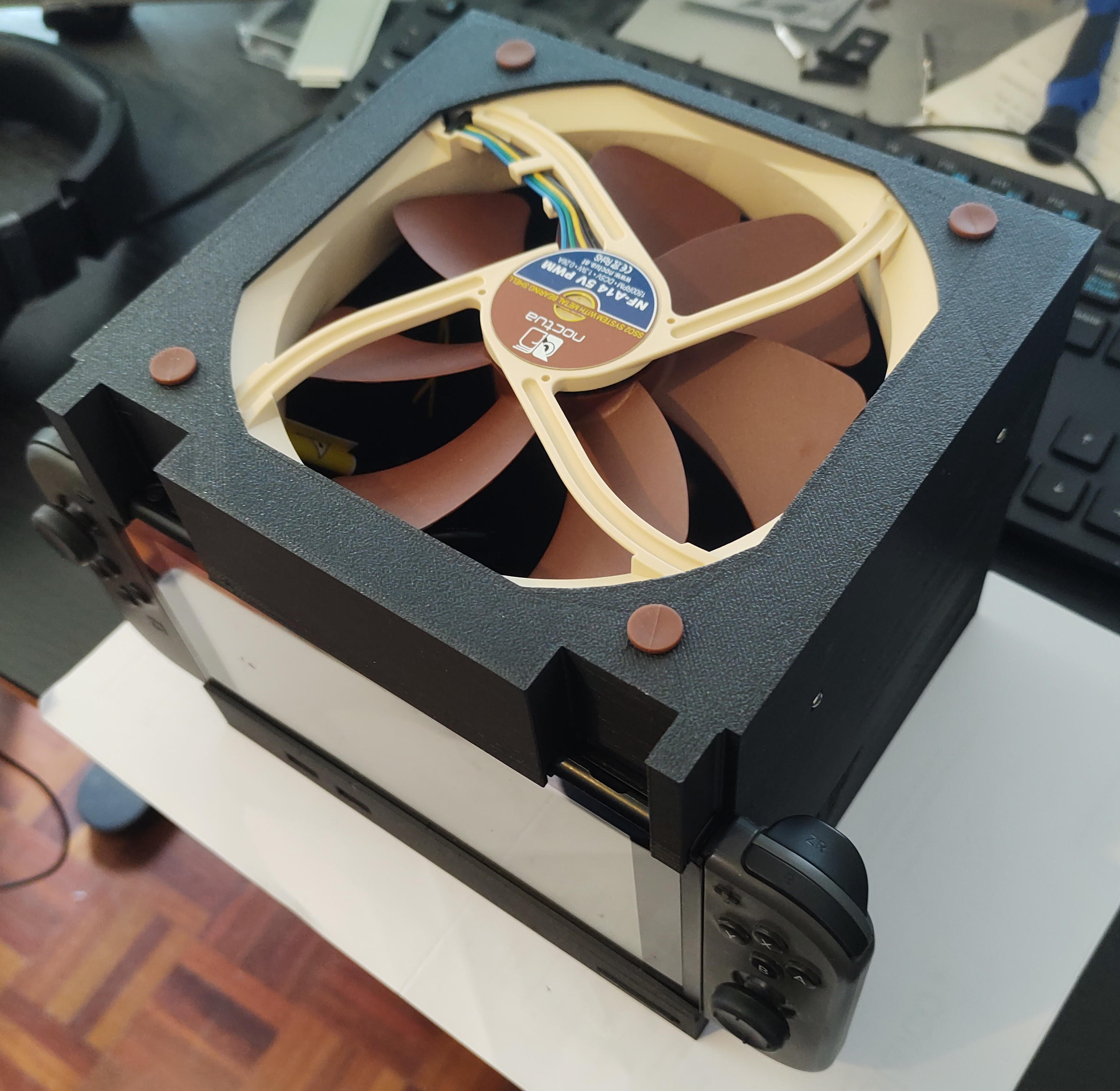
Battery-less switch. Another step in my Consolize project.

In my quest to 'consolize' a switch into a Switchn't I wanted to remove the requirement for a battery.

Not much has been done to figure this out but I did find a thread on shmups in which user fwannmacher had over time figured it out after their battery failed.

First step, there are two test points next to the battery connector (on V1 and V2 switches, yet to confirm lite or oled) that are for the Sense line and GND. Putting a 10k ohm resistor across those pads makes the switch think the battery is fully charged, and will no longer try to charge it.
Sense GND.pngComplete.JPEG

Next step, the switch requires voltage into the batt circuit or it will not turn on. A DC to DC buck converter from the 15V rail on the switch dock motherboard is a perfect solution for this.
Before connecting the buck converter to the battery input on the switch motherboard, I set its output voltage to 4.22v on my digital multimeter and then connected the output wires to the switches battery input.
15V Dock.pngFinal Assy.JPEG

Now with buck voltage output at 4.22v on meter I then dialed it in to 4320mv in Hekate (4.30v on meter), hekate has battery info under Console Info/Battery.
This screen unfortunately doesn't auto refresh, so I was making very minute adjustments on the buck converters adjustment screw, then closing and reopening the battery screen to check the new value.
(I got the value of 4320mv from a second fully charged switch I had on hand, but I recommend you check what your console is before beginning modification)
Batt Info.png


With all this complete the switch now boots completely without a battery, both into OFW and CFW.
Proof of concept.jpeg

Thanks to fwannmacher for their work. I just wanted to do a complete writeup thats a little easier to follow for people in the future and hopefully extending the lifespan of some switches.
 

dragonmaster

Ancient One
Member
Joined
Sep 9, 2005
Messages
613
Trophies
1
XP
1,671
Country
Greece
nice DIY project sadly far long away of my capabilities to mod. ( i am below average when it comes to solder) though it is very nice.
 

Imagina

Member
Newcomer
Joined
May 3, 2023
Messages
5
Trophies
0
Age
36
XP
22
Country
France
Yeah , this is what i allways feared about the battery and the dock, one day this system will be unusable, i already replaced my battery once on my 7 year old switch.... Not like previous consoles from nintendo, the gamecube or the wii / wii u, the switch is just going kaput forever when there is no battery replacement made for it in the future. While this mod for direct "plug" current make it so the lack of battery is not an issue anymore... Still not the most "every user" friendly mod to achieve.
 
  • Like
Reactions: FueledSamantha

FueledSamantha

Active Member
OP
Newcomer
Joined
Apr 4, 2023
Messages
26
Trophies
0
Age
31
XP
189
Country
Australia
I'm glad to see that my little project helped someone 🙂
Post automatically merged:

In the case you want to replace the fan here is the pinout.
View attachment 369868
Your work saved me so much headache!
I did figure out the fan pinout a few weeks ago as I do plan to eventually make another revision and try to make it smaller again using maybe a low profile GPU cooler. Anything from a card over 35W should work.
Can I wire in a USB charger wire into the wires so I can charge and play with battery backup my USB c port is fukt
No, you would start a lithium fire.
Im really, really excited by this project.
Finally having a use for heavily damaged Switch units is fantastic!

Im gonna be looking for a good deal on one of those specifically to follow in your footsteps!

Having a tiny little Switch console, constantly running at high clocks, perhaps even with improved cooling or a LAN-port by using an Oled Dock as a base and an internally hooked-up USB-HDD... i cant stop dreaming about the possibilities here!

You rock <3
A lot can be done and an oled dock version would be pretty cool as I did kill the wifi during some prototyping of coolers. (the 100nf caps left the chat)
I have gone for a bulkier route as I wanted to keep the screen for accessing Hekate and I wanted to be able to use the system for charging the Joy-Cons. Other than that I overclocked the hell of it so I have used a 140mm Noctua Fan (:
97441305-01f6-42d2-b8ff-da6b621e60f8.jpg
I was looking into integrating the joycon rails into a shell design but it was a bunch of stuffing around since I already have a charge stand for them on my controller display shelf.

This is my finalized version for the moment. Max overclocks stable at 40c in BOTW.
The power button is discrete and you just press on the shell lid lightly to activate the button on the original ribbon which made this quite a sleek design.
IMG_9065.JPEGIMG_9066.JPEG

IMG_9068.JPEGIMG_9067.JPEG


Cooling is simply two stock coolers stacked on eachother, the second held on with cable ties and a gentle sweeping bend in the heatpipe.
I used the motherboard backplate (albeit cut down) from the original chassis to mount the mainboard to as it also provides the screw points for the heatsink, fan and cart slot.
 

Imagina

Member
Newcomer
Joined
May 3, 2023
Messages
5
Trophies
0
Age
36
XP
22
Country
France
Your work saved me so much headache!
I did figure out the fan pinout a few weeks ago as I do plan to eventually make another revision and try to make it smaller again using maybe a low profile GPU cooler. Anything from a card over 35W should work.

No, you would start a lithium fire.

A lot can be done and an oled dock version would be pretty cool as I did kill the wifi during some prototyping of coolers. (the 100nf caps left the chat)

I was looking into integrating the joycon rails into a shell design but it was a bunch of stuffing around since I already have a charge stand for them on my controller display shelf.

This is my finalized version for the moment. Max overclocks stable at 40c in BOTW.
The power button is discrete and you just press on the shell lid lightly to activate the button on the original ribbon which made this quite a sleek design.
View attachment 370115View attachment 370116

View attachment 370118View attachment 370119


Cooling is simply two stock coolers stacked on eachother, the second held on with cable ties and a gentle sweeping bend in the heatpipe.
I used the motherboard backplate (albeit cut down) from the original chassis to mount the mainboard to as it also provides the screw points for the heatsink, fan and cart slot.
you should make holes for directed airflow, and add plastic sheets to "guide" the airflow to the fan acting like a conduct / AC that speeds up succion for air to travel accross critical components, like , mostly the copper chamber, if you do a good job engineering a "path" for airflow blowing and accellerating through a duct to profit from the fan natural speed air succion you can increase cooling without the need for a more powerfull fan. I do often see it like air conditionner duct pathing in a small environment, ALSO i would add a very small fan and a secondary duct path for the power supply/ condensator of your tiny power converter there if you want it to last even longer.
.
Even thou i think the plastic shell might be thin and close enough to act on itself as a duct if it's close enough to the components but the shell of the switch is much tighter and much closer to these components and act exactly this way.

And yes, making it as close as the size / thickness of the switch should be the way to go, and just finding a slightly more efficient fan of the same size and power draw should also be a very nice improvement while keeping the same small form factor.
 

FueledSamantha

Active Member
OP
Newcomer
Joined
Apr 4, 2023
Messages
26
Trophies
0
Age
31
XP
189
Country
Australia
you should make holes for directed airflow, and add plastic sheets to "guide" the airflow to the fan acting like a conduct / AC that speeds up succion for air to travel accross critical components, like , mostly the copper chamber, if you do a good job engineering a "path" for airflow blowing and accellerating through a duct to profit from the fan natural speed air succion you can increase cooling without the need for a more powerfull fan. I do often see it like air conditionner duct pathing in a small environment, ALSO i would add a very small fan and a secondary duct path for the power supply/ condensator of your tiny power converter there if you want it to last even longer.
.
Even thou i think the plastic shell might be thin and close enough to act on itself as a duct if it's close enough to the components but the shell of the switch is much tighter and much closer to these components and act exactly this way.

And yes, making it as close as the size / thickness of the switch should be the way to go, and just finding a slightly more efficient fan of the same size and power draw should also be a very nice improvement while keeping the same small form factor.
You're over complicating it, the reason you would normally need tight air paths is because the components are in a small enclosed space and cant passively dissipate their heat into the air due to the lack of air volume available. And despite that the factory airpath is in the rear vents, across the EMI shield, into the fan and out the heatsink fins. There is no airflow across any of the other componentry.
My current design (which will be revised after I play TOTK) simply takes air into the fan and exhausts it out the front of the chassis, removing hot air from the shell and pushing it out, allowing other components to continue to dissipate their heat into the air.

And the buck converter is over specked as hell so it will never overheat hahaha.
 

starlitalpha

Member
Newcomer
Joined
Apr 24, 2007
Messages
17
Trophies
1
XP
98
Country
United States
I have a question that might seem insulting at first, but I want to assure you it isn't. (hopefully my following questions will show that.)
Why do this?

The most obvious answer is to preserve future switches when the batteries are gone and there are no replacements, but I just want to know for sure. For all I know you just thought it would be a neat project and broke out the soldering iron. As it stands this is something I would never want to do because I can't count the number of times the switch being on battery saved me from losing progress due to a blackout/brownout.

Another thought I had about this though was if it would be possible to have it where it didn't require the screen. Some video only outputs to the switches screen as it is and I think for it to truly be a consolized switch, that would have to be done at some point. I imagine it has to be possible, I'm just not the person who has the knowledge or skills to say for sure.

Whatever the reason, I think it's pretty neat and I hope to see what you come up with when all is said and done.
 

fwannmacher

Active Member
Newcomer
Joined
Mar 23, 2016
Messages
37
Trophies
0
Age
36
XP
503
Country
Brazil
I have a question that might seem insulting at first, but I want to assure you it isn't. (hopefully my following questions will show that.)
Why do this?

The most obvious answer is to preserve future switches when the batteries are gone and there are no replacements, but I just want to know for sure. For all I know you just thought it would be a neat project and broke out the soldering iron. As it stands this is something I would never want to do because I can't count the number of times the switch being on battery saved me from losing progress due to a blackout/brownout.

Another thought I had about this though was if it would be possible to have it where it didn't require the screen. Some video only outputs to the switches screen as it is and I think for it to truly be a consolized switch, that would have to be done at some point. I imagine it has to be possible, I'm just not the person who has the knowledge or skills to say for sure.

Whatever the reason, I think it's pretty neat and I hope to see what you come up with when all is said and done.
In my case the reason was overclocking. I wanted to keep it cool and without stressing the fan too much (Switch's fan can get quite loud) besides the fact that it is future proof regarding the battery. Regarding the screen it is only need to access payloads such as Hekate. If you don't feel the need of accessing it after everything is set up, then you can just remove it you will be good to go.
Post automatically merged:

In my quest to 'consolize' a switch into a Switchn't I wanted to remove the requirement for a battery.

Not much has been done to figure this out but I did find a thread on shmups in which user fwannmacher had over time figured it out after their battery failed.

First step, there are two test points next to the battery connector (on V1 and V2 switches, yet to confirm lite or oled) that are for the Sense line and GND. Putting a 10k ohm resistor across those pads makes the switch think the battery is fully charged, and will no longer try to charge it.
View attachment 367366View attachment 367367

Next step, the switch requires voltage into the batt circuit or it will not turn on. A DC to DC buck converter from the 15V rail on the switch dock motherboard is a perfect solution for this.
Before connecting the buck converter to the battery input on the switch motherboard, I set its output voltage to 4.22v on my digital multimeter and then connected the output wires to the switches battery input.
View attachment 367368View attachment 367372

Now with buck voltage output at 4.22v on meter I then dialed it in to 4320mv in Hekate (4.30v on meter), hekate has battery info under Console Info/Battery.
This screen unfortunately doesn't auto refresh, so I was making very minute adjustments on the buck converters adjustment screw, then closing and reopening the battery screen to check the new value.
(I got the value of 4320mv from a second fully charged switch I had on hand, but I recommend you check what your console is before beginning modification)
View attachment 367373


With all this complete the switch now boots completely without a battery, both into OFW and CFW.
View attachment 367374

Thanks to fwannmacher for their work. I just wanted to do a complete writeup thats a little easier to follow for people in the future and hopefully extending the lifespan of some switches.
I don't know about you, but I was still getting the battery to "charge" after a while even with the 10k resistor. After some investigation I noticed that my actual resistance was 9.95k and that the resistance between sensor and ground in the battery when fully charged was 10.1k. So I added a 200 ohms resistor to the mix and so far the Switch hasn't tried to charge the battery again.
 
  • Like
Reactions: FueledSamantha

FueledSamantha

Active Member
OP
Newcomer
Joined
Apr 4, 2023
Messages
26
Trophies
0
Age
31
XP
189
Country
Australia
I have a question that might seem insulting at first, but I want to assure you it isn't. (hopefully my following questions will show that.)
Why do this?

The most obvious answer is to preserve future switches when the batteries are gone and there are no replacements, but I just want to know for sure. For all I know you just thought it would be a neat project and broke out the soldering iron. As it stands this is something I would never want to do because I can't count the number of times the switch being on battery saved me from losing progress due to a blackout/brownout.

Another thought I had about this though was if it would be possible to have it where it didn't require the screen. Some video only outputs to the switches screen as it is and I think for it to truly be a consolized switch, that would have to be done at some point. I imagine it has to be possible, I'm just not the person who has the knowledge or skills to say for sure.

Whatever the reason, I think it's pretty neat and I hope to see what you come up with when all is said and done.
I was bored, had a bunch of switches laying around, wanted to overclock the crap out of one to run TOTK smoothly without melting it. Didnt want a battery in it so it can just be chucked on a shelf and forgotten about without melting the house when I inevitably move onto something else.

I don't know about you, but I was still getting the battery to "charge" after a while even with the 10k resistor. After some investigation I noticed that my actual resistance was 9.95k and that the resistance between sensor and ground in the battery when fully charged was 10.1k. So I added a 200 ohms resistor to the mix and so far the Switch hasn't tried to charge the battery again.
I'll have to jab the meter into it and have a lookyloo next time I have it open. I'll be picking up my copy of TOTK in 24 hours.
 
  • Like
Reactions: starlitalpha

FueledSamantha

Active Member
OP
Newcomer
Joined
Apr 4, 2023
Messages
26
Trophies
0
Age
31
XP
189
Country
Australia
Now you just need to throw a microsd to sata adapter device in there and a cheap 2tb ssd.
I don't even fill a 512gb micro sd hahaha. And I doubt there would be much performance gain from an A2 card to ssd other than more consistent speed.............. (goes to aliexpress)
It would be cool to sold it to a Tv , kinda like a built in switch tv .
Instead of google chrome built in , it would be switch built in :-)
(sticks it to TV with double sided tape) Done.
Post automatically merged:

I don't know about you, but I was still getting the battery to "charge" after a while even with the 10k resistor. After some investigation I noticed that my actual resistance was 9.95k and that the resistance between sensor and ground in the battery when fully charged was 10.1k. So I added a 200 ohms resistor to the mix and so far the Switch hasn't tried to charge the battery again.
Yeah I just got this when it dropped to 84%, appears the buck converter had shifted during some assembly/disassembly down to 4.13v so I increased it to 4.28v and its now showing 100% no charge.
Yes the resistor is measuring 9.9k ohms, so I will keep an eye on it and order a couple more resistors.
 
Last edited by FueledSamantha,
  • Like
Reactions: matias3ds

fwannmacher

Active Member
Newcomer
Joined
Mar 23, 2016
Messages
37
Trophies
0
Age
36
XP
503
Country
Brazil
So, I decided about going for another direction and using the battery board instead and the result is pretty good. I set the buck converter voltage to 4.3v and now the battery is always full.
We still need a 10K resistor otherwise the battery board will tell the system that the battery's temperature is -32C. The resistor between the test points will tell the Switch that the temperature is 28C. But there is no need of extra resistors other than the 10K one - even with its error margin.
IMG_20230513_190321893_HDR.jpgIMG_20230513_205305636.jpg
 
Last edited by fwannmacher,

FueledSamantha

Active Member
OP
Newcomer
Joined
Apr 4, 2023
Messages
26
Trophies
0
Age
31
XP
189
Country
Australia
So, I decided about going for another direction and using the battery board instead and the result is pretty good. I set the buck converter voltage to 4.3v and now the battery is always full.
We still need a 10K resistor otherwise the battery board will tell the system that the battery's temperature is -32C. The resistor between the test points will tell the Switch that the temperature is 28C. But there is no need if extra resistors other than the 10K one - even with its error margin.
View attachment 371154View attachment 371164
I've been sinking too many hours into TOTK to look further into it, but now I'm gonna have to sacrifice a battery I guess XD
Wonder how small we can package it now that we know this.
 

fwannmacher

Active Member
Newcomer
Joined
Mar 23, 2016
Messages
37
Trophies
0
Age
36
XP
503
Country
Brazil
I've been sinking too many hours into TOTK to look further into it, but now I'm gonna have to sacrifice a battery I guess XD
Wonder how small we can package it now that we know this.
Yeah, TotK is taking my time as well xD
The nice part of using the battery PCB is that it delivers less voltage than its input. So we can have 4.6v as input and it will deliver 4.3v. So I'm trying to find a better voltage line than 15.35v - like using a 5v from usb - so we can ditch the buck converter completely.
 

FueledSamantha

Active Member
OP
Newcomer
Joined
Apr 4, 2023
Messages
26
Trophies
0
Age
31
XP
189
Country
Australia
Yeah, TotK is taking my time as well xD
The nice part of using the battery PCB is that it delivers less voltage than its input. So we can have 4.6v as input and it will deliver 4.3v. So I'm trying to find a better voltage line than 15.35v - like using a 5v from usb - so we can ditch the buck converter completely.
Hrm, now I want to do a revision 2 but im out of functioning mainboards lol.
 

fwannmacher

Active Member
Newcomer
Joined
Mar 23, 2016
Messages
37
Trophies
0
Age
36
XP
503
Country
Brazil
I have tried using a 5V line but the USB ports from the dock have a very low current. So it ends in a unstable solution.
 

Attachments

  • dock board.png
    dock board.png
    908.1 KB · Views: 61
Last edited by fwannmacher,

FueledSamantha

Active Member
OP
Newcomer
Joined
Apr 4, 2023
Messages
26
Trophies
0
Age
31
XP
189
Country
Australia
It might be worth taking the BMS PCB off the battery itself, and basically just keep the cell off the circuit. See if that keeps the Switch happy.
So, I decided about going for another direction and using the battery board instead and the result is pretty good. I set the buck converter voltage to 4.3v and now the battery is always full.
We still need a 10K resistor otherwise the battery board will tell the system that the battery's temperature is -32C. The resistor between the test points will tell the Switch that the temperature is 28C. But there is no need of extra resistors other than the 10K one - even with its error margin.
View attachment 371154View attachment 371164

This looks the go, I sacrificed a battery and integrated the BMS with the buck converter feeding it, and im no longer having the batt% changing over longer gaming sessions. When I get around to trying a revision 2 i'll see how much the BMS can be cut down.
 
  • Love
Reactions: fwannmacher

Site & Scene News

Popular threads in this forum

General chit-chat
Help Users
    SylverReZ @ SylverReZ: @salazarcosplay, I'm good. Thanks.