Measuring things in circuit is hard as you are also measuring the rest of the circuit (see parallel resistances, and the rest of the circuit effectively counts as one). Not so bad if it is a high resistance elsewhere but lower stuff/lower resistance path makes it tricky.
To do it properly you would have to at least remove one leg, though many go for straight removal. You can also do high frequency measurements as impedance around the rest of the circuit is often equivalent to high resistance (in normal hobbyist circles you might have an ESR meter for measuring dead capacitors, this is a high frequency resistance measuring device) but you won't necessarily get the out of circuit values of these as much as a variation on the theme - no simple values you can go to your stores/chosen electronics vendor and buy some cut tape from.
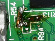
Pity they did not have any numbers on top, don't look scrubbed but guess they are too small for the usual three number setup of SMD resistors (
https://www.basictables.com/electronics/resistor/smd-resistor-code ).
I am not aware of any schematics that have been generated (nobody having fun like
https://circuit-board.de/forum/index.php/Thread/13913-STRIP-CLUB-PCB-Scans/?pageNo=1 with DSi just yet, hopefully in a year or two we see DSi being basically given away like I had original DS and DS lites the other year, and GBAs up until about 4 years ago), leaked (nothing in the various gigaleaks that I saw) or otherwise made available.
If you can figure out what it is connected to (though I guess that is a nice BGA component nearby so have fun with that) then you might see if the circuit in question is basically the reference circuit from the manual.


![IMG_3839[1].JPG](/data/attachments/271/271781-74b7ceeb7cdd22208221c4b6e8e66764.jpg)