Tutorial  Updated

Trinket Internal Install.

Here's A Guide To Installing The Trinket M0 Into The Switch.

Program The Trinket Before You Remove The Usb Port, Saves You Doing It After You Complete The Install.

First Thing To Do Is Remove The Usb Port From The Trinket, If You Have A Hot Air Wand Then Use That To Remove The Port It Will Reduce The Risk Of Damage To The Pads.

usb intact.jpg


Now That The Usb Port Has Been Removed You Want To Solder Wire To The Data Pads, White = Data- And Green Data+ In This Guide.

Now Solder Wire To The Bat Pad = Red, Gnd Pad = Black, Pad 4 = Orange & Pad 3 = Brown In This Guide.

Also Remove The Resistor Next To The Ppower Led Mark Out In Purple In This Guide.
Trinket Points.jpg


When You Have The Trinket All Prepared, You Can Now Proceed To The Install To The Switch.
trinket install points.jpg


Once The Install Is Completely Done Then Clean Up The Points You Have Soldered To Using Isopropyl And Cotton Buds/Q-Tips.
Finished.jpg


Alternative Point For Pad 4.

Altternative Pad 4 Point.jpg


Alternative Points For Joycon Rail Pin 10.

If You Decide On Using This Alternative Point Then Use Enamel Coated Jumper Wire 0.10mm.

Alt Joycon Rail Pin 10 Point.jpg


Remember Take Your Time It's Not A Race lol. Rushing Can Lead To Mistakes.

Tools Required.

Kynar Wire 30 AWG.
Soldering Iron.
Hot Air Wand For Usb Port Removal(Optional)
Isopropyl.
Cotton Bud/Q-Tips.
Flux.
Solder.
Enamel Jumper Wire (Optional)


Thanks And Credit Goes To Xboxexpert For This Solution.

I Think That Covers Everything.

EDIT..

here's another method for the install of the trinket, this method does away with the pad 4, as some may find it tricky to solder to the cap used on the mobo.

the rst pad is used instead and the wire is linked to the power button, Also this has a bonus that you can double press the power button to put the trinket into boot loader mode for uploading a new payload.

of course you don't have to use the rst pad at all, you can't just press power button and volume up button, then press reset button for rcm mode.

this method should be ok for the novices.

install at your own risk.

another install.jpg


the pad on the power button to use.

power button point.jpg


i have one more method to try but I really think this one is not to bad method.

the more methods the better I say, of course to try and make it as easy as possible for pros and novices.

EDIT...
another method for the install of the trinket.

this method is basically same as all other methods, just a different points uses for the bat pad and rst pad.

this install will allow you to have the trinket power off when you fully power off the switch.

double press the reset button on the trinket to get into boot loader mode, this may take a couple of attempts to do.

the payload that you use already will work with this method no need for new ones.

here's the diagram for method 3, you could possibly have this as a 4 wire install, if you install auto rcm mode, but as my sd card module port is buggerd I couldn't test that out.

twinket power off.jpg


ok it seems method 3 needs auto rcm installed for it to work without the need to use the rst pad

so for them that don't want to use auto rcm mode then solder a wire from rst pad to the point on the power button, and use pad 3 to the pin 10 on the joycon rail or one of the alt points on mobo.

beware the alt points are small so use at your own risk.

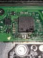
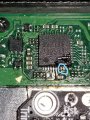
ok anyone with changing issues test these 2 points, you should get 5v on the usb port side, and around 3.2v on the switch side.

if your getting the volts on the switch side that are fluctuating up & down then replace the part with the v on top it's a diode, you want one that fits so the actual size is either 0402 or 0603 in dimension (i'm using 0402/0603 as an example for size purpose only)

around page 16 has more info about this component..

dont come moaning if you damage your console doing this install, i'm not responsible for you opening or taking a soldering iron to your console.
you do this at your own risk any damage is down to yourself.


charger_issue_volts.jpg


another thing if your trinket starts to get very hot to the point you can't touch it, then the atmel ATSAMD21E18A-U ic is on it's way out, so you will need to replace the ic or just replace your trinket.

at some point it wont power up after this has happened.
1 = gets very hot.
2 = reset starts to become tempermental .
3 = dead
4 = fix replace the atmel ATSAMD21E18A-U ic

edit

added uf2 drag and drop files for r4 trinket gemma dongles or for a 4 wire internal install.

atmosphere
hekate 4.2
Sxos
rajnx
reinx
 

Attachments

  • Trinket All In One.jpg
    Trinket All In One.jpg
    123.9 KB · Views: 4,030
  • Trinket-R4-Gemma-D&D-Files.zip
    421.3 KB · Views: 579
Last edited by M-O-B, , Reason: added updated uf2 file.

mrdude

Developer
Developer
Joined
Dec 11, 2015
Messages
3,071
Trophies
1
Age
56
XP
8,227
I'm still confused because you said we need a 2A Diode but the last time I connected the power supply with the Diode jumpered I got 15v into the switch and the power supply says it’s 2.6A at 15V so if we use a 2A diode it seams to be to low and the original power supply would destroy the diode after a few minutes of usage if it really outputs 2.6A.

That just means the power supply is capable of outputting that much - 39watts (15x2.6), it doesn't mean the switch is going to use all that, when running an extreme high CPU intensive game on the switch, with docked and charging at the same time.

The Switch dock itself plays host to 3 USB Type-A ports, including a USB 3.0 port on the rear. As a result the power adapter for the Switch apparently needed to be quite a bit over-sized to ensure that it never faces a load larger than it can handle. Besides running the Switch, it also potentially needs to be able to power a USB hard drive and charge a couple of Pro Controllers, all of which can add up quickly.

It wouldn't hurt to put a larger diode in IE something that can handle 3 amps and 15 volts or even higher if you wanted as the function of the diode is just to stop reverse polarity.

When Nintendo or any other company make circuits, they choose to use the cheapest parts possible, putting in a part that over exceeds what they need adds expense which cuts their profits down.

If you're overly worried about that diode I posted you a link to - use some common sense and search for a better part that you think you need. (although it's a waste to put a porche engine in a car, where in that country the speed limit is 10mph.)
 
Last edited by mrdude,

Ferris1000

Well-Known Member
Member
Joined
Mar 10, 2017
Messages
251
Trophies
0
Age
33
Location
Titan
XP
2,380
Country
Germany
That just means the power supply is capable of outputting that much - 39watts (15x2.6), it doesn't mean the switch is going to use all that, when running an extreme high CPU intensive game on the switch, with docked and charging at the same time.

The Switch dock itself plays host to 3 USB Type-A ports, including a USB 3.0 port on the rear. As a result the power adapter for the Switch apparently needed to be quite a bit over-sized to ensure that it never faces a load larger than it can handle. Besides running the Switch, it also potentially needs to be able to power a USB hard drive and charge a couple of Pro Controllers, all of which can add up quickly.

It wouldn't hurt to put a larger diode in IE something that can handle 3 amps and 15 volts or even higher if you wanted as the function of the diode is just to stop reverse polarity.

When Nintendo or any other company make circuits, they choose to use the cheapest parts possible, putting in a part that over exceeds what they need adds expense which cuts their profits down.

If you're overly worried about that diode I posted you a link to - use some common sense and search for a better part that you think you need. (although it's a waste to put a porche engine in a car, where in that country the speed limit is 10mph.)
But if the diode is just to stop reverse polarity why the voltage is 3.2v on the opposite side ? I used a standard 1n4148 diode just to check the voltage and it was almost 5v instead of 3.2v...I know it’s the wrong one and the Diode got very hot but I didn’t care because it was a 1cent diode
 

Lil_SpazJoekp

Well-Known Member
Newcomer
Joined
Apr 11, 2018
Messages
89
Trophies
0
Age
28
XP
383
Country
United States
thanks thats have me all info i needed without the guess work..

--------------------- MERGED ---------------------------


it might be helpful if you actually post images of your install and trinket, rather than people trying to guess at what the issue could be.

nothing wrong with 30awg wire so that wont be your issue.

this is nothing like installing a crappy ace v3 or coolrunner into a 360 any fool can install them buggers
Let me get some breakfast and then I will crack open the switch for some pics. The chip I was installing was the CR4 XL if you were curious.
 

efxonly123

Well-Known Member
Newcomer
Joined
Jul 13, 2018
Messages
99
Trophies
0
Age
51
XP
321
Country
United States
this was no fun to fix, when people tend to use big ass irons at 60w then your going to damage stuff
View attachment 135732

but a short time later someone will be happy, now I'll install his trinket just so i don't have to see a mess like this again.

View attachment 135730

4.7uf cap and 10k resistors i used as them was the only 0402 i had in stock, i would think you get away with using 1k, during this fix i also noticed that the damaged trace did not seem to stop the console from working via the dock at all, it was the missing cap that stopped it from charging & working from the dock.

View attachment 135735


that is 99% the diode the quick way to test if it is the diode, just bridge it with a jumper wire. ( test purposes only) do not leave the jumper wire on permanent. as soon as you tested if it works via the dock and external charger then remove the jumper wire and buy a replacement diode.

Thanks M-O-B, when you say bridge the diode, do you mean run a wire from one side of the diode to the other side of the same diode? Also you mention that the one you fixed was missing a capacitor that stopped it from charging and working from the dock, I had my 3v wire going to that same capacitor in the pic after removing the cap above it, so I'll test that cap as well.

--------------------- MERGED ---------------------------

The capacitor up top is likely just for filtering. If the diode shows up fine and you see the proper voltage on both ends then we can work on testing the charge controller. usually it's just the diode that blows almost like a fuse which makes it an easy and cheap fix.
Thanks Captain_Smek, I'm going to test that diode again today, but I did purchase a pack of 50 diodes just in case that's the issue.
 
  • Like
Reactions: Deleted User

M-O-B

Well-Known Member
OP
Member
Joined
Jun 23, 2018
Messages
281
Trophies
0
Age
54
XP
583
Country
United Kingdom
But if the diode is just to stop reverse polarity why the voltage is 3.2v on the opposite side ? I used a standard 1n4148 diode just to check the voltage and it was almost 5v instead of 3.2v...I know it’s the wrong one and the Diode got very hot but I didn’t care because it was a 1cent diode

if your getting 5v on both sides then the diode is wrong one or ain't working correctly.

by the time you've messed about trying whatever diodes, you could have gotten the correct one and had it fitted, closed up and not bothering with it again.

Thanks M-O-B, when you say bridge the diode, do you mean run a wire from one side of the diode to the other side of the same diode? Also you mention that the one you fixed was missing a capacitor that stopped it from charging and working from the dock, I had my 3v wire going to that same capacitor in the pic after removing the cap above it, so I'll test that cap as well.

--------------------- MERGED ---------------------------


Thanks Captain_Smek, I'm going to test that diode again today, but I did purchase a pack of 50 diodes just in case that's the issue.

yeah one side of the diode to the other side bridge to test only.

as for the cap best posting a image of the area that way people can help better without the guessing.

as for the cap that was missing on the repair I did, witch was the one below the pad 4 one used. that was the one that stopped the switch from doing anything at all in the dock.

I think you said you not getting charge from external and dock and the led on the dock blinks.

that tells me it's the diode.
 

efxonly123

Well-Known Member
Newcomer
Joined
Jul 13, 2018
Messages
99
Trophies
0
Age
51
XP
321
Country
United States
if your getting 5v on both sides then the diode is wrong one or ain't working correctly.

by the time you've messed about trying whatever diodes, you could have gotten the correct one and had it fitted, closed up and not bothering with it again.


yeah one side of the diode to the other side bridge to test only.

as for the cap best posting a image of the area that way people can help better without the guessing.

as for the cap that was missing on the repair I did, witch was the one below the pad 4 one used. that was the one that stopped the switch from doing anything at all in the dock.

I think you said you not getting charge from external and dock and the led on the dock blinks.

that tells me it's the diode.

Hello M-O-B, I tried testing that diode again near the usb and I'm not getting any reading from it. My multimeter detects a signal from the switch side of that diode to ground spots on the board, and the I get a signal from usb side of that diode to some prongs on the usb C connecter. When I bridge the diode, the switch still does not charge.

--------------------- MERGED ---------------------------

The capacitor up top is likely just for filtering. If the diode shows up fine and you see the proper voltage on both ends then we can work on testing the charge controller. usually it's just the diode that blows almost like a fuse which makes it an easy and cheap fix.

Hello Captain_Smek, I posted a reply to M-O-B regarding the diode testing and I wanted you to chime in also.
 
D

Deleted User

Guest
Hello M-O-B, I tried testing that diode again near the usb and I'm not getting any reading from it. My multimeter detects a signal from the switch side of that diode to ground spots on the board, and the I get a signal from usb side of that diode to some prongs on the usb C connecter. When I bridge the diode, the switch still does not charge.

--------------------- MERGED ---------------------------


Hello Captain_Smek, I posted a reply to M-O-B regarding the diode testing and I wanted you to chime in also.
So no voltage at all on either the 3.3v and 5v side? You mentioned signal, as in continuity?

Just for clarity the switch powers on and functions aside from not taking a charge right?
 

efxonly123

Well-Known Member
Newcomer
Joined
Jul 13, 2018
Messages
99
Trophies
0
Age
51
XP
321
Country
United States
So no voltage at all on either the 3.3v and 5v side? You mentioned signal, as in continuity?

Just for clarity the switch powers on and functions aside from not taking a charge right?

Correct, I couldn't get a voltage from either side, but there was continuity from the switch side of the diode with ground points throughout the switch, and the usb side of the diode has continuity with 2 or 3 prongs on the usb connector. It powers up and functions properly, but doesn't charge through the dock or external charger. I'm sure when I tested it yesterday or the day before, there was voltage on both sides but I think one side was not showing correctly. Now no voltage on either side.
 
Last edited by efxonly123,

mrdude

Developer
Developer
Joined
Dec 11, 2015
Messages
3,071
Trophies
1
Age
56
XP
8,227
@efxonly123

It's pretty obvious to me that if you don't have any voltage - either your charger is broken or your usb port is broken, plug a usb cable from your laptop/computer into your switch and see if you get any voltage then, if you do - your charger is broken, if not your port is broken.
 
D

Deleted User

Guest
Correct, I couldn't get a voltage from either side, but there was continuity from the switch side of the diode with ground points throughout the switch, and the usb side of the diode has continuity with 2 or 3 prongs on the usb connector. It powers up and functions properly, but doesn't charge through the dock or external charger. I'm sure when I tested it yesterday or the day before, there was voltage on both sides but I think one side was not showing correctly. Now no voltage on either side.

Ok that's not sounding too great =/ Any chance you are able to send a good photo of the capacitor from point 4. If it's back in working order we might have to check back to the charge controller chip, unless @M-O-B has anything else to suggest. I'll have one apart in a few hours so I can throw some numbers at you for testing if nobody gets back to you sooner.
 

efxonly123

Well-Known Member
Newcomer
Joined
Jul 13, 2018
Messages
99
Trophies
0
Age
51
XP
321
Country
United States
@efxonly123

It's pretty obvious to me that if you don't have any voltage - either your charger is broken or your usb port is broken, plug a usb cable from your laptop/computer into your switch and see if you get any voltage then, if you do - your charger is broken, if not your port is broken.

Hello mrdude, when I plug the usb cable from the computer to the switch nothing is recognized by windows, however the usb side of the diode reads 5v and the switch side of the diode reads about 2.5v. When I was reading the switch side of the diode, a popup came on my pc stating that there was a usb overload occuring. Does it sound like I have a bad charger chip (m92t36)?

--------------------- MERGED ---------------------------

Ok that's not sounding too great =/ Any chance you are able to send a good photo of the capacitor from point 4. If it's back in working order we might have to check back to the charge controller chip, unless @M-O-B has anything else to suggest. I'll have one apart in a few hours so I can throw some numbers at you for testing if nobody gets back to you sooner.

Here's a pic. I still have not put the capacitor back on yet.
 

Attachments

  • 20180714_220809.jpg
    20180714_220809.jpg
    1.6 MB · Views: 176

M-O-B

Well-Known Member
OP
Member
Joined
Jun 23, 2018
Messages
281
Trophies
0
Age
54
XP
583
Country
United Kingdom
Hello M-O-B, I tried testing that diode again near the usb and I'm not getting any reading from it. My multimeter detects a signal from the switch side of that diode to ground spots on the board, and the I get a signal from usb side of that diode to some prongs on the usb C connecter. When I bridge the diode, the switch still does not charge.

--------------------- MERGED ---------------------------


Hello Captain_Smek, I posted a reply to M-O-B regarding the diode testing and I wanted you to chime in also.


I'm not sure if your testing the diode correct or not, but if your getting continuity to gnd from the diode then that indicates some sort of short, if I'm reading your post correctly that is.

so I would post images of the points you have solder any wires to.
 
  • Like
Reactions: Deleted User

efxonly123

Well-Known Member
Newcomer
Joined
Jul 13, 2018
Messages
99
Trophies
0
Age
51
XP
321
Country
United States
I'm not sure if your testing the diode correct or not, but if your getting continuity to gnd from the diode then that indicates some sort of short, if I'm reading your post correctly that is.

so I would post images of the points you have solder any wires to.

For some reason, I feel that there's a short somewhere. In the pic I posted, and in some of the pics you posted, there's a very small capacitor near the m92t36 chip on the same side as the 3.3v pad. Both sides of the very small capacitor have continuity with ground and 2 legs of the ic chip directly above that same capacitor also have continuity with ground. I don't see a bridge there though.
 

M-O-B

Well-Known Member
OP
Member
Joined
Jun 23, 2018
Messages
281
Trophies
0
Age
54
XP
583
Country
United Kingdom
Hello mrdude, when I plug the usb cable from the computer to the switch nothing is recognized by windows, however the usb side of the diode reads 5v and the switch side of the diode reads about 2.5v. When I was reading the switch side of the diode, a popup came on my pc stating that there was a usb overload occuring. Does it sound like I have a bad charger chip (m92t36)?

Here's a pic. I still have not put the capacitor back on yet.

you will need to replace that missing cap 4.7uf.

also it's difficult to tell from the image but looks like you have some solder balls between some components, but that may be the camera flash playing tricks.

20180715_031742.jpg
 
  • Like
Reactions: Deleted User

efxonly123

Well-Known Member
Newcomer
Joined
Jul 13, 2018
Messages
99
Trophies
0
Age
51
XP
321
Country
United States
If you're getting 5v when you plug into a laptop - then the try with the charger and get nothing - your charger is broken.

When you say the charger may be broken, do you mean the m92t36 chip that is broken?

--------------------- MERGED ---------------------------

you will need to replace that missing cap 4.7uf.

also it's difficult to tell from the image but looks like you have some solder balls between some components, but that may be the camera flash playing tricks.

View attachment 135850
Yeah, one of them is definitely a solder ball. Hopefully the microscope I get tomorrow will help me locate any other solder balls. I circled a small capacitor and 2 ic legs. Can you tell me if those should go to ground?
 

Attachments

  • Inked20180714_220809_LI.jpg
    Inked20180714_220809_LI.jpg
    1.7 MB · Views: 140
Last edited by efxonly123,

M-O-B

Well-Known Member
OP
Member
Joined
Jun 23, 2018
Messages
281
Trophies
0
Age
54
XP
583
Country
United Kingdom
When you say the charger may be broken, do you mean the m92t36 chip that is broken?

i do believe it will not charge with that cap missing, so you are going to have to replace it first before you can carry on with anymore testing.

solder a wire to the 3.2v pad then a wire to any gnd point, then solder a cap to the two wires, this will be the easiest way to test if it is indeed the missing cap that is the issue.

if everything works fine then replace the cap properly.

ipa and a soft toothbrush will clean any solder balls away.

20180715_033416.jpg
 
Last edited by M-O-B,
  • Like
Reactions: Deleted User

efxonly123

Well-Known Member
Newcomer
Joined
Jul 13, 2018
Messages
99
Trophies
0
Age
51
XP
321
Country
United States
i do believe it will not charge with that cap missing, so you are going to have to replace it first before you can carry on with anymore testing.

solder a wire to the 3.2v pad then a wire to any gnd point, then solder a cap to the two wires, this will be the easiest way to test if it is indeed the missing cap that is the issue.

if everything works fine then replace the cap properly.

ipa and a soft toothbrush will clean any solder balls away.

View attachment 135852

Ok, thank you. I will most likely tackle it again on monday when I get some 34 awg wire and some better solder. Also, any comment on this pic regarding this small capacitor and both sides having continuity with ground?
 

Attachments

  • Inked20180714_220809_LI.jpg
    Inked20180714_220809_LI.jpg
    1.7 MB · Views: 184

Site & Scene News

Popular threads in this forum

General chit-chat
Help Users
    Psionic Roshambo @ Psionic Roshambo: Lol