OLED Switch “A” CMD Resistor - Half Damaged Pad

OctuplePrecision

Member
OP
Newcomer
Joined
Aug 17, 2020
Messages
10
Trophies
0
Age
28
XP
153
Country
United States
Hello,

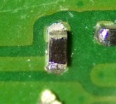
When working on modding an OLED Switch, I ended up lifting part of the pad my wire was attached to (I'm using 30 gauge wire as part of an INSTINCT V6 install). I've attached a photo of the top of the resistor I soldered for the A/CMD point. I think I was using too much heat and tugged on the wire before it was properly cooled.

The resistor (4.7k 0201) is still firmly attached to the Switch motherboard, and I haven't attempted to put the console back together yet to see if it will boot into the original firmware. I was wondering if there are any other points I could tap into for the A/CMD line. I can test by re-assembling the console as is (without soldering the other ends of the wire to the mod chip) and seeing if it boots fully, indicating the resistor is fine. But if there's no alternative point for the A/CMD line, I need to remove the 0201 4.7k resistor and attempt to repair the pad.

I hope to use Kapton tape to insulate the area around the damaged pad, then use hot air, lift the old resistor off (any suggestions on temperature for the hot air?) and then use what's left of the pad for the repair. I have some 3M Copper Shielding Tape 1125 and pad repair strips. I might use the pad repair strips over the tape, but either should work. I'd use some solder to bridge between the tape/pad and what's left of the original trace. I'd use UV solder mask to bond the repair to the PCB, and then I should be able to place a new 0201 4.7k resistor and the A/CMD wire and finish this install.

All the other points went well; I found the D/CLK point tricky. I scraped gently with an xacto and used a 30 gauge wire there. I could get solid adhesion with the solder, but it felt fragile. I had some PCB-safe RTV162 (used for supporting large capacitors) to give it some more support and a dab of superglue further downstream of the wire to reduce strain on the joint itself.

Any suggestions would be appreciated as well, as well as any way to use a multimeter to check my work concerning the other points (I've seen some posts about diode values)

Thanks!
 

Attachments

  • A_CMD_SwitchOLED.jpeg
    A_CMD_SwitchOLED.jpeg
    1 MB · Views: 64
Last edited by OctuplePrecision,

randy_w

Well-Known Member
Member
Joined
Feb 27, 2021
Messages
709
Trophies
0
Age
34
XP
1,373
Country
United States
I don't see any damage to the A point. Maybe you just pulled the wire and the wire took some solder away with it. If you are unsure add a bit more solder to the bottom pad, should be good.

If I were you I'd partly assemble the switch (only attach screen and power button ribbon cables and battery) and see if it boots to OFW. Don't fix it if it ain't broken. Also the bottom pad goes about 3 layers deep and directly to Tegra SoC. If you damage it it's game over:
https://balika011.hu/switch/oled/

I usually use those green UV glue to secure D point, although I've seen people doing it without any support.
Always use a multimeter to check connections in diode mode before powering it on with modchip. Correct values should be:
A, C, D: 0.5-0.8V
B: 2-3V, might be OL if your meter can't push high enough voltage in diode mode
SP1/SP2: one side ground, the other side is very low (0.02V iirc), but not short to ground
 

OctuplePrecision

Member
OP
Newcomer
Joined
Aug 17, 2020
Messages
10
Trophies
0
Age
28
XP
153
Country
United States
I don't see any damage to the A point. Maybe you just pulled the wire and the wire took some solder away with it. If you are unsure add a bit more solder to the bottom pad, should be good.

If I were you I'd partly assemble the switch (only attach screen and power button ribbon cables and battery) and see if it boots to OFW. Don't fix it if it ain't broken. Also the bottom pad goes about 3 layers deep and directly to Tegra SoC. If you damage it it's game over:
https://balika011.hu/switch/oled/

I usually use those green UV glue to secure D point, although I've seen people doing it without any support.
Always use a multimeter to check connections in diode mode before powering it on with modchip. Correct values should be:
A, C, D: 0.5-0.8V
B: 2-3V, might be OL if your meter can't push high enough voltage in diode mode
SP1/SP2: one side ground, the other side is very low (0.02V iirc), but not short to ground
Sorry, I had the photo flipped the wrong way around; I edited my post to reflect the correct orientation.

When I tried to add more solder to the pad, I couldn’t get any solder to adhere. I’m using Amtech tacky flux and Kester leaded solder, and I tried a wider tip to get a little more heat into it. I think the only portion of the pad that’s left is the bit under the resistor, I tried to see if it was possible to attach a wire to the side of the resistor, but I had no luck with that. I’ll do as you mentioned and give it a quick test and see if the OFW launches (thanks for telling me the minimum complements needed to boot the console)

Perhaps that might be the easiest repair option, swap the resistor out and then attach a wire to the side of the resistor. Though, as you mentioned, it’s perilous.

Thanks for the info about the diode values; I’ll give it a good once-over before powering it up. I know my DAT0 was reading 0.6v in diode mode so I’m sure that’s sorted. The green UV would have been a good idea for the D point, I didn’t have any on hand then. I think the RTV162, when fully cured, will be strong enough, but I could always go back and fix that.
 

randy_w

Well-Known Member
Member
Joined
Feb 27, 2021
Messages
709
Trophies
0
Age
34
XP
1,373
Country
United States
1689058204293.png


The silver part looks like solder, not fiberglass so I guess the pad is still intact. The joint does look a bit cold though, maybe your iron temperature is too low since it's lead free solder. I usually use 350C, and crank up another 20-30C when using extra fine tips.
 

OctuplePrecision

Member
OP
Newcomer
Joined
Aug 17, 2020
Messages
10
Trophies
0
Age
28
XP
153
Country
United States
View attachment 382750

The silver part looks like solder, not fiberglass so I guess the pad is still intact. The joint does look a bit cold though, maybe your iron temperature is too low since it's lead free solder. I usually use 350C, and crank up another 20-30C when using extra fine tips.
Okay, thanks for the info! I’ll give a shot and report back!
Post automatically merged:

I didn't get a chance to test re-assemble the console yet, but I was able to attempt to add solder to the pad. I had a fresh narrow tip, iron around 375C, and used a healthy amount of flux. I couldn't get anything to bond to the pad save for the very edge; I had solder very quickly attaching to the other side of the resistor, as well as solder easily flowing to the 30 gauge wire, but there was no adhesion between the pad and the solder, at least not in any way that would offer some support.

Looking back, I think the photo wasn't the best I provided; I rotated the board to allow the light to catch it at a different angle and adjusted the contrast to better express what I was seeing. The area marked by pink 1 shows the only location solder would grab to, but it's not enough to try and hold anything down; the area marked by blue 2 shows the missing pad area.

I will make time tomorrow to test the console and see if it boots into the OFW. I just ran out of time trying to get a better photo to show the damage better. It feels like; at this point, the only option would be to remove that resistor and try and repair the pad. I was reluctant to put it together again, given the wires are all dangling but I'll trim them to the right length and put it back together.

Given how solid the resistor feels, there’s still a lot of the pad attached, but clearly I’d have to be very careful to make sure the temperature is at just the right point, and maybe even look into using solder paste to re attach the resistor, just to minimize the amount of pressure I put on that pad. Open to any and all suggestions, and I’ll report back once I can test boot the console.

IMG_9559.jpeg
 
Last edited by OctuplePrecision,

randy_w

Well-Known Member
Member
Joined
Feb 27, 2021
Messages
709
Trophies
0
Age
34
XP
1,373
Country
United States
Oh shit at this angle it does look like part of the pad is gone, and I can see the fiberglass base. Part of the resistor is gone too.

1689136303488.png
1689136321143.png

However, the pad underneath is pretty large compared to the damaged area, so I guess the part under the resistor is still intact.

If I were you, I'd test the switch and see if it boots. If it does, solder wire to the remaining part of the resistor, or scratch solder mask away and solder wire to the remaining pad and call it a day:
1689136589119.png


If your console doesn't boot, then remove the resistor with hot air and assess the damage. Hopefully you only need to replace the resistor.
 
  • Like
Reactions: OctuplePrecision

OctuplePrecision

Member
OP
Newcomer
Joined
Aug 17, 2020
Messages
10
Trophies
0
Age
28
XP
153
Country
United States
Oh shit at this angle it does look like part of the pad is gone, and I can see the fiberglass base. Part of the resistor is gone too.

View attachment 382908View attachment 382909
However, the pad underneath is pretty large compared to the damaged area, so I guess the part under the resistor is still intact.

If I were you, I'd test the switch and see if it boots. If it does, solder wire to the remaining part of the resistor, or scratch solder mask away and solder wire to the remaining pad and call it a day:
View attachment 382910

If your console doesn't boot, then remove the resistor with hot air and assess the damage. Hopefully you only need to replace the resistor.
Yeah, I was able to confirm this by finally getting a chance to boot the console today. I got the pink/purple screen, so that’s the resistor gone for the A point. I‘ve ordered some of the right size, 0201 4.7k, and I’ll give it a go this weekend if I find time. I’ve got an old DS I’ll try and get my eye in when working with the smaller components. I’ve done this kind of repair before with hot air, and it’s not been bad, but it’s just been a little bit, and I don’t want to make this worse than it is.

Do you have any recommendations on what kind of temperature I should use with the air? I was thinking about 150C to warm the board around it and then bumping it to about 350C to lift it off. I’ll use Kapton tape around the area and some foil as a shield.
Post automatically merged:

SMD resistor normally have u shape conductor on both end. Looks like the A point conductor already broken so you would need a new 4.7k OHM resistor
Thanks for the input, yeah that end was just lifted off when I tugged on the wire too aggressively.

I’ve got some 4.7k resistors of 0201 size, and I‘ll give it a go this weekend. I’m going to use hot air, and tape around the board with kapton tape and foil to insulate the rest of the area from the heat and not blow anything else off. I’ll warm the area around at 150C, and then bump it up to 350C and slightly poke it with my tweezers till it floats off easily. I’ll use plenty of flux as well.
 
Last edited by OctuplePrecision,

Sabinx7

Member
Newcomer
Joined
Jul 24, 2016
Messages
7
Trophies
0
Age
38
XP
48
Country
Mexico
Yeah, I was able to confirm this by finally getting a chance to boot the console today. I got the pink/purple screen, so that’s the resistor gone for the A point. I‘ve ordered some of the right size, 0201 4.7k, and I’ll give it a go this weekend if I find time. I’ve got an old DS I’ll try and get my eye in when working with the smaller components. I’ve done this kind of repair before with hot air, and it’s not been bad, but it’s just been a little bit, and I don’t want to make this worse than it is.

Do you have any recommendations on what kind of temperature I should use with the air? I was thinking about 150C to warm the board around it and then bumping it to about 350C to lift it off. I’ll use Kapton tape around the area and some foil as a shield.
Post automatically merged:


Thanks for the input, yeah that end was just lifted off when I tugged on the wire too aggressively.

I’ve got some 4.7k resistors of 0201 size, and I‘ll give it a go this weekend. I’m going to use hot air, and tape around the board with kapton tape and foil to insulate the rest of the area from the heat and not blow anything else off. I’ll warm the area around at 150C, and then bump it up to 350C and slightly poke it with my tweezers till it floats off easily. I’ll use plenty of flux as well.
Something similar but worse happened to me (didn't took photo because of shame).
Mine came off completely because I had the same issue and pushed the wire against it to make it square and force solder into it to grab the pad,thing is when it came off it stuck to the soldering tip and removed it fast with my tweezers and flew off somewhere into a dark hole or something.
Thing is that purple screen is when everything is correct but that point becomes loose, console is still good. It happened to me several times when tried to do a fast mod and could not measure good distance for the heatsink and would end up pushing the chip making that point break off.

Getting to my point, I was able to make it work again a couple of times (even without the resistor) soldering the wire directly to the non existing pad, because I had to dig a bit into it to get some metal to show, after the 3rd or 4th it was just a black screen or it would boot to OFW, but everything worked as of now, my guess is that some low voltage came through the wire and made it boot into hekate, and after a couple of boots, voltage depleted making it pulse purple again like training but boot into OFW, but operational.

I will try to post picture on Monday to show my progress and result to see if I can help you fix your console.
 

Site & Scene News

Popular threads in this forum

General chit-chat
Help Users
  • No one is chatting at the moment.
    K3Nv2 @ K3Nv2: Lol rappers still promoting crypto