

Tutorial
Updated
NAND Dumping 2DS/3DS/3DS XL/N3DS/N3DS XL!
Hardmodding 3DS Family Systems
This is a tutorial for those who want to perform a NAND dump (or a "hardmod") of their 3DS/2DS/N3DS console(s).
This tutorial is mainly directed towards those who are new to the 3DS scene and want to dump their NAND to be able to easily restore later. This is for all of the 3DS models currently available: 3DS, 3DS XL, New 3DS, New 3DS XL, and 2DS. This hardmod is useful for a myriad of reasons, not limited to just having a backup of your system in case you brick it. For the purpose of brevity, I will refer to these systems as simply "3DS" from here on when I am actually referring to any of these consoles in general.
If you have been on the 3DS scene for a while, you have may heard the terms 'hardmod' or 'NAND Dump'. A NAND is a type of flash memory that is used, in the case of the 3DS, to store important information such as firmware. The firmware is retrieved from the NAND by the bootloader when the console is powered on. One question I get asked commonly is if a NAND dump from one system can be flashed onto another system. However, the NAND is encrypted with a key that is specific to each console. Therefore, this is not possible. Hardmodding your 3DS will add a level of protection: knowing that you can simply flash the NAND dump back onto your system if it ever gets bricked. I would advise keeping your NAND file someplace safe after dumping, such as a cloud service. You never know if/when you are going to need it, and if you ever get bricked and you do not have a NAND dump available, there is no going back. You have been warned.
Before we begin the tutorial, it is CRUCIAL that you know/have experience soldering. There are many videos on YouTube on how to solder, and I will link a few at the end of this guide. Soldering takes practice to learn and get the hang of, so don't just blindly jump into modding without a solid understanding of soldering, because most likely YOU WILL BREAK YOUR DEVICE
This is a compilation of information about hardmodding each 3DS system. The majority of the information below is a detailed explanation of how to install a hardmod based on the NAND pinout images that are on 3DBrew. I am by no means an expert on this topic and I am still learning the inner workings of it all. If you have any questions, please feel free to comment below and I will try answer them. To begin, here are some of the advantages and some of the disadvantages of a hardmod:
Advantages:
- You will have a full backup of your 3DS firmware, so that you will be able to restore your NAND if you accidentally brick your 3DS during the downgrading process.
- The tools are relatively inexpensive to perform the hardmod.
- The hardmod may cause problems if you are not careful: It may even lead to bricking your device!
- Solder splashes can be harmful as well: they may short circuit other things.
- Soldering experience is required, even though this is very simple, make sure you are fully acquainted with soldering before even attempting to come anywhere near your 3DS with your soldering iron. A solid grasp of soldering techniques will greatly help you and make sure your 3DS does not become an expensive piece of trash.
Now, for the tools:
- A soldering iron: One with a fine tip
- Solder: I use rosin core 60/40 solder. Do NOT use acid core, as this is corrosive to the motherboard and can screw things up.
- Tinning Flux
- Phillips #000 screwdriver or JIS #000: Phillips #000 or JIS #000 screwdrivers are recommended. You can also use Phillips #00 or JIS #00, but you may strip the screws if you are not careful.
- win32diskimager program on your computer
- Wires: I personally recommend you use these wires, but if you dont want them, you can just use wires ripped out from earbuds and then buy seperate butt connectors for them. All you need to do is to solder four wires onto the male end of the connector.
- microSD Card Adapter
- **microSD Card Reader: NOTE: ONLY CERTAIN TYPES OF READERS WILL WORK. MORE INFORMATION ON THIS BELOW.
- Hot Glue Gun/ Super glue: This is necessary if you plan on making this a permanent mod on your 3DS. This is used to glue on the butt connector of the wire.
- Tweezers
- A brain
Contents
Old 3DS XL Tutorial
Old 3DS Tutorial
2DS Tutorial
NEW 3DS
NEW 3DS XL
*NEW 2DS XL
Important Links/Videos
Old 3DS XL Tutorial
Old 3DS Tutorial
2DS Tutorial
NEW 3DS
NEW 3DS XL
*NEW 2DS XL
Important Links/Videos
STEPS FOR OLD 3DS XL CONSOLE:
IMPORTANT NOTE: There are only certain SD card readers confirmed working with this mod for 3DS XL:
IMPORTANT NOTE: There are only certain SD card readers confirmed working with this mod for 3DS XL:
Anker® USB 3.0 (68UNMCRD-B2U) : Realtek RTS5306
TekRepublic TUC-300 : Realtek RTS5307
SanDisk SDDR-121-A11M : GL827
Transcend P8 TS-RDP8K : ALCOR AU6476 (Thank you Gamerquest1 and zchtoy)
Anker® USB 3.0 4-Slot Card Reader (A7612) : RT5301 (Ava)
(The "Anker" readers have been highly tested by me and others who have performed a hardmod. They are confirmed to work with the Old 3DS. Therefore, the "Anker" readers are best recommended to work with this hardmod)
- Remove all peripherals from the console and store them someplace safe
- Flip the console over and unscrew the two screws on top securing the back plate. Note: These screws do not come off completely; they remain attached to the back plate. Remove the back plate by hinging it outward
- Once the back plate is removed, you need to remove the 3DS XL battery
- Now remove the six screws that hold the back cover in place. Keep these somewhere safe.
- Once all the screws are removed, the 3DS XL PCB will be exposed. DO NOT FORCEFULLY FLIP THE COVER OPEN. There are still two ribbon cables attached to the motherboard. Gently flip the back cover over and detach the ribbon cables using your fingernail. Place the back cover aside.
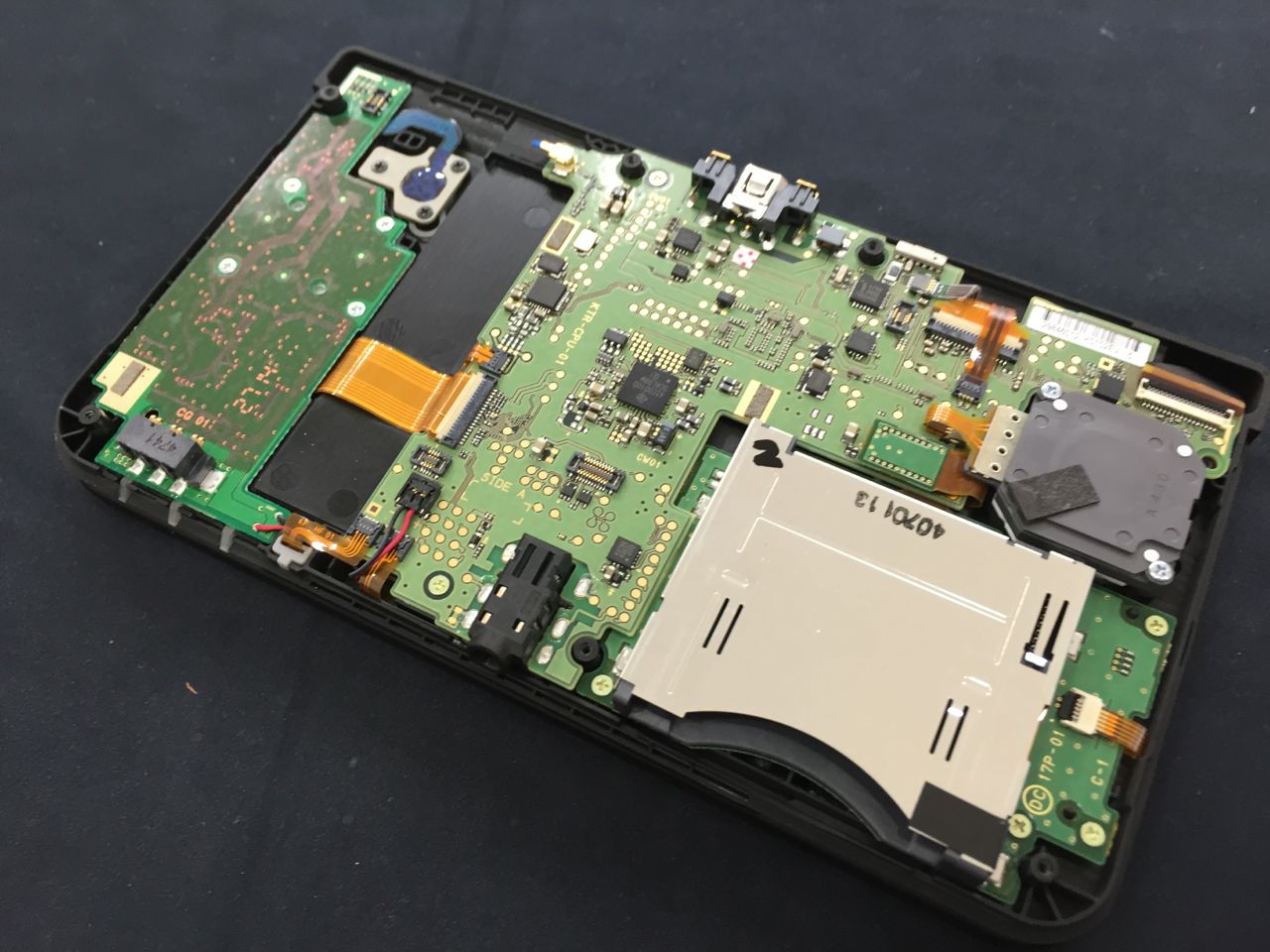
- Once you have done that, get your wires and all the other materials you need to begin soldering. You will be working near the NAND: There are 4 main contacts that you will be soldering to. The top one is the DAT0 (Data Zero), the next one is CMD, and the next one is CLK (Clock). Over to the left, you will see some solder: This can serve as GND (Ground). The NAND chip in the following picture has been removed to see the points easier. You can find these points near the chip to the right of the game card slot. The other DAT contacts (DAT1, DAT2, and DAT3) are not required, but you can solder to them if you are looking for faster transfer speeds. This is beyond the scope of this tutorial, but the basic principle is the same except you now need 7 wires with a connector and you need to solder the extra DAT points on the microSD adapter.


- Apply some tinning flux to the end of your wire and use the wire as a brush to apply it onto the contacts that you will be soldering on. You could also use a q-tip to apply the flux to the contacts. This will make your soldering job easier.
- Begin soldering the four wires to each of the contacts: DAT0, CMD and CLK, and also GND (the solder blob). Make sure your soldering is clean, neat, and make sure you soldered the right points.
- Once you have triple checked that your solder work is perfect, cut a hole onto the back cover (not the back plate) of your 3DS console to place the butt connecter to the wires. If you are using the wires that I recommended, the connectors are already provided. You can make a hole by drilling it in or using your soldering iron to melt a hole. Then, you can finish it off using a hand file. Once you have made a hole for the butt connector, use a hot glue gun (or superglue) to glue the butt connecter to the back cover. Only apply the hot glue to the INSIDE of the back cover.
- Turn on your 3DS system to make sure that it still works properly and you didn’t kill it.
- Grab your microSD card adapter. It is time we solder the wires to it. If you are using my recommended wires, grab the second set of wires that came with the package. I highly, highly recommend that you color code the wires (one color for GND, another for CMD, CLK, and DAT0). Open your microSD adapter by using your fingernail to pry open the casing. Pull out the chip inside.
- You will see 8 pins inside the adapter. Solder the wires to the respective pins according to the diagram below. The diagram here shows a different point for Ground. You can also use that point or the solder blob. I use the solder blob because it is closer.
- Now, once you have done that, it is time for the software portion. Plug your SD adapter into the recommended reader, but DO NOT plug the reader into the computer...yet.
- Power on your 3DS. If you did everything right, there should be a bootrom error message on a blue screen. In this state, you are now able to read/write the NAND. Do not power off your 3DS, and plug the reader into the USB port of your computer.
- On your computer, right click win32diskimager and select "Run as Administrator". Type in your administrator password and the program will open.
- Name the file whatever you want, but make sure you end it in (.img), so the program recognizes it as a Disk Image File. For example, you can name it NAND.img. Click on "Read". This process will take a few minutes. If you want to ever restore your NAND dump back to your device, then choose the disk image file and click on "Write" instead of "Read".
- Your NAND should now be successfully dumped! Make sure to check the file sizes of the NAND to see if the dump was completed successfully.


STEPS FOR 2DS
IMPORTANT NOTE: There are only certain SD card readers confirmed working with this mod for 2DS. Note that they are the same as the New 3DS:
Anker® USB 3.0 (68UNMCRD-B2U) : Realtek RTS5306
TekRepublic TUC-300 : Realtek RTS5307
Some other card readers that use the same chipset /controller but have not been tested although should work:
Plugable USB3-FLASH3 -
SIIG JU-MR0E12-S1-
Startech FCREADMICRO3 -
Other card readers that work
SanDisk SDDR-121-A11M : GL827
Anker® USB 3.0 4-Slot Card Reader (A7612) : RT5301 (Ava)
(The "Anker" readers have been highly tested by me and others who have performed a hardmod. They are confirmed to work with the Old 3DS. Therefore, the "Anker" readers are best recommended to work with this hardmod)
- Remove all peripherals from the console and store them someplace safe
- Flip the console over and unscrew the two screws on top securing the back plate. Note: These screws do not come off completely; they remain attached to the back plate. Remove the back plate:
- Once the back plate is removed, you need to remove the 2DS battery
- Now remove the ten 1.587mm screws that hold the back cover in place. Keep these somewhere safe.
- Once all 10 screws are removed, the 2DS PCB will be exposed. DO NOT FORCEFULLY FLIP THE COVER OPEN. There is still a ribbon cable attached to the back cover. Gently flip the back cover over and unscrew the two .793mm screws attaching the ribbon cable to the back panel. Place the back cover aside.
- Once you have done that, get your wires and all the other materials you need to begin soldering. You will be working near the NAND: There are 4 main contacts that you will be soldering to. They are DAT0 (Data Zero), CMD, CLK (Clock), and we will use the metal SD card shielding for GND (Ground). The other DAT contacts (DAT1, DAT2, and DAT3) are not required, but you can solder to them if you are looking for faster transfer speeds. This is beyond the scope of this tutorial, but the basic principle is the same except you now need 7 wires with a connector and you need to solder the extra DAT points on the microSD adapter. All of these contacts are located on the opposite side of the motherboard. Flipping the motherboard may be a bit tedious and difficult to do, so here is a link that goes into detail on how to do it rather than me typing it here: https://www.ifixit.com/Guide/Nintendo+2DS+Motherboard+Replacement/35842
- Apply some tinning flux to the end of your wire and use the wire as a brush to apply it onto the contacts that you will be soldering on. You could also use a q-tip to apply the flux to the contacts. This will make your soldering job easier and prevent oxidation.
- Begin soldering the four wires to each of the contacts: DAT0, CMD and CLK, and also GND (the SD shielding). Make sure your soldering is clean, neat, and make sure you soldered the right points.
- Once you have triple checked that your solder work is perfect, cut a hole onto the back cover (not the back plate) of your 2DS console to place the butt connecter to the wires. If you are using the wires that I recommended, the connectors are already provided. You can make a hole by drilling it in or using your soldering iron to melt a hole. Then, you can finish it off using a hand file. Once you have made a hole for the butt connector, use a hot glue gun (or superglue) to glue the butt connecter to the back cover. Only apply the hot glue to the INSIDE of the back cover.
- Turn on your 2DS system to make sure that it still works properly and you didn’t kill it.
- Grab your microSD card adapter. It is time we solder the wires to it. If you are using my recommended wires, grab the second set of wires that came with the package. I highly recommend that you color code the wires (one color for GND, another for CMD, CLK, and DAT0). Open your microSD adapter by using your fingernail to pry open the casing. Pull out the chip inside.
- You will see 8 pins inside the adapter. Solder the wires to the respective pins according to the diagram below. The diagram here shows a picture of the 3DS XL PCB. Disregard that, as this is for 2DS, and focus on the SD card diagram and where each wire should be soldered.
- Now, once you have done that, it is time for the software portion. Plug your SD adapter into the recommended reader, but DO NOT plug the reader into the computer...yet.
- Power on your 2DS. If you did everything right, there should be a bootrom error message on a blue screen. In this state, you are now able to read/write the NAND. Do not power off your 2DS, and plug the reader into the USB port of your computer.
- On your computer, right click win32diskimager and select "Run as Administrator". Type in your administrator password and the program will open.
- Name the file whatever you want, but make sure you end it in (.img), so the program recognizes it as a Disk Image File. For example, you can name it NAND.img. Click on "Read". This process will take a few minutes. If you want to ever restore your NAND dump back to your device, then choose the disk image file and click on "Write" instead of "Read".
- Your NAND should now be successfully dumped! Make sure to check the file sizes of the NAND to see if the dump was completed successfully.


STEPS FOR OLD 3DS
IMPORTANT NOTE: There are only certain SD card readers confirmed working with this mod for 3DS (Same as XL) :
IMPORTANT NOTE: There are only certain SD card readers confirmed working with this mod for 3DS (Same as XL) :
Anker® USB 3.0 (68UNMCRD-B2U) : Realtek RTS5306
TekRepublic TUC-300 : Realtek RTS5307
SanDisk SDDR-121-A11M : GL827
Transcend P8 TS-RDP8K : ALCOR AU6476 (Thank you Gamerquest1 and zchtoy)
Anker® USB 3.0 4-Slot Card Reader (A7612) : RT5301 (Ava)
(The "Anker" readers have been highly tested by me and others who have performed a hardmod. They are confirmed to work with the Old 3DS. Therefore, the "Anker" readers are best recommended to work with this hardmod)
- Remove all peripherals from the console and store them someplace safe where the homeless won't find them
- Flip the console over and unscrew the four screws on top securing the back plate. Note: These screws do not come off completely; they remain attached to the back plate. Remove the back plate by gently prying it apart.
- Once the back plate is removed, you need to remove the 3DS battery
- Now remove the nine 6.3mm screws that hold the back cover in place. Keep these somewhere safe. Don't forget the screw on the gamecard slot.
- Once all 9 screws are removed, the 3DS PCB will be exposed. DO NOT FORCEFULLY FLIP THE COVER OPEN. There are still two ribbon cables attached to the motherboard. Gently flip the back cover over and detach the ribbon cables using your fingernail. Place the back cover aside.
- This next step involves flipping the motherboard, as the NAND chip is located on the back side of the motherboard. For the purpose of brevity, I have omitted the details on how to disassemble the motherboard properly to flip it, as this is beyond the scope of this tutorial. You can Google this, or look at video teardowns of the old 3DS on YouTube.
- Once you have done that, get your wires and all the other materials you need to begin soldering. You will be working near the NAND: There are 4 main contacts that you will be soldering to. They are DAT0 (Data Zero), CMD, and CLK (Clock). The other DAT contacts (DAT1, DAT2, and DAT3) are not required, but you can solder to them if you are looking for faster transfer speeds. This is beyond the scope of this tutorial, but the basic principle is the same except you now need 7 wires with a connector and you need to solder the extra DAT points on the microSD adapter. There are two points that can serve as GND (Ground). The first is a contact near the game card slot, and the other is a solder blob. Pick whichever one you want. As you can see, CLK is underneath the card reader. To access it, you must desolder the 3 legs of the card reader and slightly bend up. This may be a bit tough, so there is also another CLK point you can use that is on the opposite side of the motherboard .

- Apply some tinning flux to the end of your wire and use the wire as a brush to apply it onto the contacts that you will be soldering on. You could also use a q-tip to apply the flux to the contacts. This will make your soldering job easier.
- Begin soldering the four wires to each of the contacts: DAT0, CMD and CLK, and also GND (the solder blob or the contact). Make sure your soldering is clean, neat, and make sure you soldered the right points.
- Once you have triple checked that your solder work is perfect, cut a hole onto the back cover (not the back plate) of your 3DS console to place the butt connecter to the wires. If you are using the wires that I recommended, the connectors are already provided. You can make a hole by drilling it in or using your soldering iron to melt a hole. Then, you can finish it off using a hand file. Once you have made a hole for the butt connector, use a hot glue gun (or superglue) to glue the butt connecter to the back cover. Only apply the hot glue to the INSIDE of the back cover.
- Turn on your 3DS system to make sure that it still works properly and you didn’t kill it.
- Grab your microSD card adapter. It is time we solder the wires to it. If you are using my recommended wires, grab the second set of wires that came with the package. I highly, highly recommend that you color code the wires (one color for GND, another for CMD, CLK, and DAT0). Open your microSD adapter by using your fingernail to pry open the casing. Pull out the chip inside.
- You will see a few pins inside the adapter. Solder the wires to the respective pins according to the diagram below.

- Now, once you have done that, it is time for the software portion. Plug your SD adapter into the recommended reader, but DO NOT plug the reader into the computer...yet.
- Power on your 3DS. If you did everything right, there should be a bootrom error message on a blue screen. In this state, you are now able to read/write the NAND. Do not power off your 3DS, and plug the reader into the USB port of your computer.
- On your computer, right click win32diskimager and select "Run as Administrator". Type in your administrator password and the program will open.
- Name the file whatever you want, but make sure you end it in (.img), so the program recognizes it as a Disk Image File. For example, you can name it NAND.img. Click on "Read". This process will take a few minutes. If you want to ever restore your NAND dump back to your device, then choose the disk image file and click on "Write" instead of "Read".
- Your NAND should now be successfully dumped! Make sure to check the file sizes of the NAND to see if the dump was completed successfully.


STEPS FOR NEW 3DS
NOTE: Only the following SD card readers work with the New 3DS! (Not the same as the Old 3DS models):
Anker® USB 3.0 (68UNMCRD-B2U) : Realtek RTS5306
TekRepublic TUC-300 : Realtek RTS5307
Some other card readers that use the same chipset /controller but have not been tested although should work:
Plugable USB3-FLASH3 -
SIIG JU-MR0E12-S1-
Startech FCREADMICRO3 -
Other card readers that work
SanDisk SDDR-121-A11M : GL827
Transcend P8 TS-RDP8K : ALCOR AU6476 (Thank you Gamerquest1 and zchtoy)
(Due to complaints about the Transcend reader not being compatible, it has been removed from this list. It is recommended that you use one of the other readers)
Anker® USB 3.0 4-Slot Card Reader (A7612) : RT5301 (Ava)
(The "Anker" readers have been highly tested by me and others who have performed a hardmod. They are confirmed to work with the New 3DS. Therefore, the "Anker" readers are best recommended to work with this hardmod)
Card reader chipsets known not to work on N3DS with the Samsung eMMC, but may still work on one with the Toshiba and the 3DS/XL eMMC:
GL3220
GL3233
GL834
- Remove all peripherals from the console and store them someplace where the homeless won't find them.
- Remove the back plate of the console by unscrewing the top two screw that secure it. Note: These do not remove completely, they still remain attached to the motherboard.
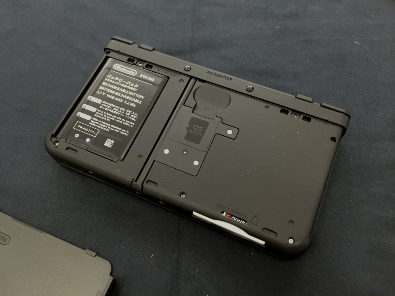
- Remove the battery. Now, unscrew the three screws that secure the microSD card reader. The New 3DS motherboard will now be exposed. BE CAREFUL!! There is still a ribbon cable underneath the microSD card reader. Carefully detach them with your fingernail.
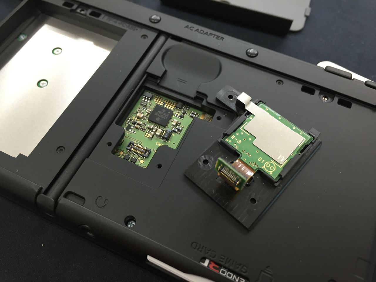
- Remove the 5 screws that are on the border of the console and carefully open the back case of the New 3DS. Additionally, there should be two rubber pegs at the top of your console. Remove them with tweezers, and unscrew the two screws that are underneath. Carefully flip the back casing open. There are still two ribbon cables underneath, so detach them with your fingernail. You should have now exposed the whole motherboard.
- The next step involves flipping the motherboard to access the NAND on the other side. This is beyond the scope of this tutorial. For a detailed guide on disassembling the motherboard, look here: https://www.ifixit.com/Guide/Nintendo+3DS+XL+2015+Motherboard+Replacement/41361. Warning! The NEW 3DS and the NEW 3DS XL have certain clips that do NOT open. These clips are shown in this picture (taken by pbanj). The cables simply pull out. Do not attempt to bend these clips to open them. Click here for a fix if you accidentally bend these clips.

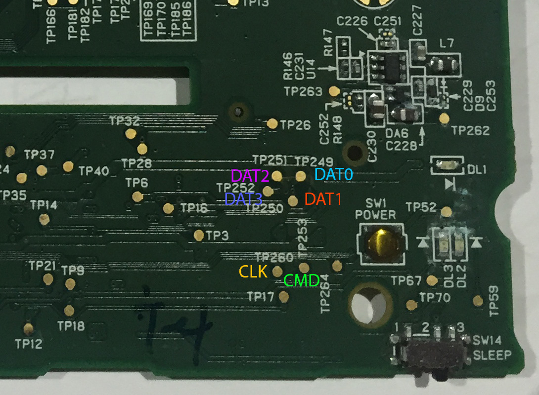
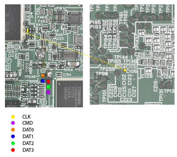
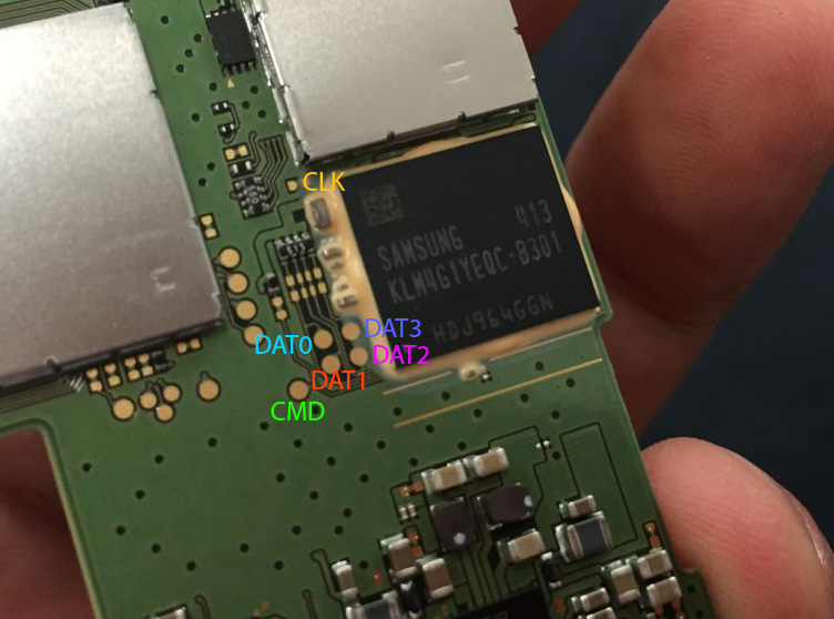
- The following image shows the NAND pinout for the New 3DS. We will only be soldering to DAT0, CMD, CLK and also ground (GND) You can simply use the metal game card shielding for GND. Just solder to a corner of the game card shielding. The other DAT contacts (DAT1, DAT2, and DAT3) are not required, but you can solder to them if you are looking for faster transfer speeds. This is beyond the scope of this tutorial, but the basic principle is the same except you now need 7 wires with a connector and you need to solder the extra DAT points on the microSD adapter. NOTE: Here is a link to a thread with details about an alternative CLK point for the New 3DS.
- Now, it is time to mount the butt connector. You can pick any place to mount it. You can use your soldering iron to melt a hole, and then use a hand file to finish it off. Once that is done, hot glue the butt connector to the hole. If you are using my recommended wires, then the butt connectors are already attached. If not, you will have to manually solder wires to a separate butt connector.
- Grab your SD card adapter and pry it open using your fingernail. Place the casing aside and pull out the actual adapter itself. If you are using my recommended wires, then grab the second set of wires that came in the package and solder each wire according to the diagram below. If not, then you must solder a butt connector to one end and solder the other ends of the wire to the SD adapter shown in the diagram below.

- Once you have created your Franken-SD Adapter, connect the butt connectors together, and then put the makeshift microSD adapter into the SD reader (Make sure you have one of the readers from the list above!). DO NOT plug the SD reader into your computer yet…
- Turn on the N3DS console. If everything went well, you should be on a blue bootrom error screen. In this state, the NAND can be read/written to. Now, without powering off your device, plug the SD reader into the USB port of your computer.
- Your computer may ask you if you want to format your NAND. DO NOT DO THIS. EVER. IT WILL DESTROY YOUR DEVICE. CLICK CANCEL. Now, right click on win32diskimager and select “Open as Administrator”. Once it is open, type whatever you want to name your file and make sure you add (.img) at the end. For example, you can name it nand.img. Click on "Read".
- Your NAND should now be successfully dumped! Make sure to check the file sizes of the NAND to see if the dump was completed successfully.
STEPS FOR NEW 3DS XL
NOTE: Only the following SD card readers work with the New 3DS XL! (Not the same as the Old 3DS models):
Anker® USB 3.0 (68UNMCRD-B2U) : Realtek RTS5306
TekRepublic TUC-300 : Realtek RTS5307
Some other card readers that use the same chipset /controller but have not been tested although should work:
Plugable USB3-FLASH3 -
SIIG JU-MR0E12-S1-
Startech FCREADMICRO3 -
Other card readers that work
SanDisk SDDR-121-A11M : GL827
Transcend P8 TS-RDP8K : ALCOR AU6476 (Thank you Gamerquest1 and zchtoy)
(Due to complaints about the Transcend reader not being compatible, it has been removed from this list. It is recommended that you use one of the other readers)
Anker® USB 3.0 4-Slot Card Reader (A7612) : RT5301 (Ava)
(The "Anker" readers have been highly tested by me and others who have performed a hardmod. They are confirmed to work with the New 3DS XL. Therefore, the "Anker" readers are best recommended to work with this hardmod)
Card reader chipsets known not to work on N3DS with the Samsung eMMC, but may still work on one with the Toshiba and the 3DS/XL eMMC:
GL3220
GL3233
GL834
- Remove all peripherals from the console and store them someplace where the homeless won't find them.
- Remove the back plate of the console by unscrewing the top two screw that secure it. Note: These do not remove completely, they still remain attached to the motherboard.
- Remove the 6 screws that are on the border of the console. Additionally, there should be two rubber pegs at the top of your console. Remove them with tweezers, and unscrew the two screws that are underneath. Carefully flip the back casing open. There are still two ribbon cables underneath, so detach them with your fingernail. You should have now exposed the whole motherboard.
- The following image shows the NAND pinout for the New 3DS XL. These pinouts are located on the other side of the board. You will need to flip the motherboard to access them. Warning! The NEW 3DS and the NEW 3DS XL have certain clips that do NOT open. These clips are shown in this picture (taken by pbanj). The cables simply pull out. Do not attempt to bend these clips to open them. Click here for a fix if you accidentally bend these clips.
- We will only be soldering to DAT0, CMD, CLK and also ground (GND) You can simply use the metal game card shielding for GND. Just solder to a corner of the game card shielding. The other DAT contacts (DAT1, DAT2, and DAT3) are not required, but you can solder to them if you are looking for faster transfer speeds. This is beyond the scope of this tutorial, but the basic principle is the same except you now need 7 wires with a connector and you need to solder the extra DAT points on the microSD adapter. An alternate CLK point is also provided
- DO NOT use this area for GND because of the power connector in blue near it:
- Now, it is time to mount the butt connector. You can pick any place to mount it. You can use your soldering iron to melt a hole, and then use a hand file to finish it off. Once that is done, hot glue the butt connector to the hole. If you are using my recommended wires, then the butt connectors are already attached. If not, you will have to manually solder wires to a separate butt connector.
- Grab your SD card adapter and pry it open using your fingernail. Place the casing aside and pull out the actual adapter itself. If you are using my recommended wires, then grab the second set of wires that came in the package and solder each wire according to the diagram below. If not, then you must solder a butt connector to one end and solder the other ends of the wire to the SD adapter shown in the diagram below.
- Once you have created your Franken-SD Adapter, connect the butt connectors together, and then put the makeshift microSD adapter into the SD reader (Make sure you have one of the readers from the list above!). DO NOT plug the SD reader into your computer yet…
- Turn on the N3DS XL console. If everything went well, you should be on a blue bootrom error screen. In this state, the NAND can be read/written to. Now, without powering off your device, plug the SD reader into the USB port of your computer.
- Your computer may ask you if you want to format your NAND. DO NOT DO THIS. EVER. IT WILL DESTROY YOUR DEVICE. CLICK CANCEL. Now, right click on win32diskimager and select “Open as Administrator”. Once it is open, type whatever you want to name your file and make sure you add (.img) at the end. For example, you can name it nand.img. Click on "Read".
- Your NAND should now be successfully dumped! Make sure to check the file sizes of the NAND to see if the dump was completed successfully.


STEPS FOR THE NEW 2DS XL
I currently do not have an in-depth tutorial for the New 2DS XL system. Little is documented about the NAND of this system, and I personally have not attempted to do a hardmod on this device. However, NAND pinouts for the New 2DS XL system have been found, and a full tutorial for this particular system can be found in this video. Once enough people have tested these pinouts, I will do an actual tutorial for the New 2DS XL:
Warning! Many people have not tested these pinouts for the New 2DS XL. 3DBrew has not documented the NAND pinouts for this system either. As such, follow this video at your own risk. I am not to be held responsible for any damage that you do to your system by following an unofficial video tutorial.
Important Links:
NAND Error Codes
3DBrew has documented details about the 3DS NAND, including other useful information. Here is a list of all the error codes that is shown by the ARM9 bootrom when the NAND isn't initialized during startup (including when you have a franken-SD attached):
NAND Sizes
This shows the different NAND sizes for 3DS consoles
Old 3DS XL NAND Dump Video Pt 1
A video tutorial on hardmodding the Old 3DS XL Part 1
Old 3DS XL NAND Dump Video Pt 2
A video tutorial on hardmodding the Old 3DS XL Part 2
How to Solder (for beginners)
A video that teaches soldering concepts to beginners. Make sure you become proficient in soldering and have attempted it before you solder your 3DS
Hardmod Installers
For those who want somebody to install a hardmod on your 3DS console, this link shows trusted hardmod installers by region (UK, France, Germany, USA, Italy, and Brazil).
Last edited by TheToaster,


