Hacking Hardware Picofly - a HWFLY switch modchip

Uberfish

Active Member
Newcomer
Joined
Jan 5, 2014
Messages
44
Trophies
0
Location
Tangerang
XP
101
Country
Indonesia
View attachment 378462

Now you only need to check using multimeter, each pin goes to where.

The one that goes to the picofly is the Gate(G).

I remember that on the flex pin theres also the D part and the S/GND part.
You might test it using multimeter to know which pin.

From that you could check the D and S part should be like 12Ohms. And the S to GND should be zero ohms. And the D to GND should be 12ohms.

This is why i think that the hwfly design is good. I could add in the firmware to detect whether the connection is correct or not, since D, S, and G is given to the board. But picofly original design didn't so only G comes to the picofly. And we couldn't detect the condition of the connection of D and S. We assume the installer already installed it correctly.
Well, I have good and bad news.

Good news: the flex cable wasn't attached correctly. I resoldered and fixed it. Now it works. The CMD caps were actually good. I was a dumbass and didn't set the correct range on my multimeter. They were actually okay and showed the correct range (4.7k and 47k).

Now for the bad news. Firstly I think the black screen is because I screwed up the display cable port. I must have used the wrong angle when trying to push it in after the install and now it looks like the image below. I can also see markings on the display flex cable, so I think two pins are bent. THIS is what is causing the black screen.

Next, I decided to reassemble and power on without the display to test the mod anyway. The chip still doesn't function as expected. It blinks blue for a loooong time, then there's a white flash and it continues to blink blue for about a minute. After that it shows === (glitch limit reached?). It could also be *** but I have no comparison on long/short flash.


I'm guessing I 100% need to replace the oled connector now. But as for the glitch, is it caused by no display, or is there something else since I do get a white flash before it keeps trying.
 

Attachments

  • display 2.jpg
    display 2.jpg
    103.9 KB · Views: 28
  • display.jpg
    display.jpg
    171.2 KB · Views: 36
  • Pico white.mp4
    2.6 MB
  • Pico error.mp4
    31.9 MB

unchil

Member
Newcomer
Joined
Jun 17, 2023
Messages
10
Trophies
0
Age
33
XP
75
Country
Poland
Hi, I have been getting this error code on a new picofly install: =*** eMMC init failure

I have been reading 0.7V on dat0, but I reseated the adapter just in case and I still get the error. If I disconnect dat0 from the picofly i get =* D0 is not connected instead.

Is this a sign of a bad dat0 adapter/connection or could something else be causing the issue?
I have a similar problem, new pico install, and =*** flashes. I read 1.79v on dat0.
=* when d0 is disconnected.
v2.74
I am using v1 flex
 
Last edited by unchil,
  • Like
Reactions: Danook28

Danook28

Well-Known Member
Member
Joined
Jul 17, 2018
Messages
500
Trophies
0
Age
34
XP
1,044
Country
Oman
Well, I have good and bad news.

Good news: the flex cable wasn't attached correctly. I resoldered and fixed it. Now it works. The CMD caps were actually good. I was a dumbass and didn't set the correct range on my multimeter. They were actually okay and showed the correct range (4.7k and 47k).

Now for the bad news. Firstly I think the black screen is because I screwed up the display cable port. I must have used the wrong angle when trying to push it in after the install and now it looks like the image below. I can also see markings on the display flex cable, so I think two pins are bent. THIS is what is causing the black screen.

Next, I decided to reassemble and power on without the display to test the mod anyway. The chip still doesn't function as expected. It blinks blue for a loooong time, then there's a white flash and it continues to blink blue for about a minute. After that it shows === (glitch limit reached?). It could also be *** but I have no comparison on long/short flash.


I'm guessing I 100% need to replace the oled connector now. But as for the glitch, is it caused by no display, or is there something else since I do get a white flash before it keeps trying.
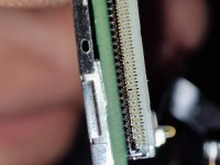
The one reson that lcd conector damge is start remove lcd Flex from up by slide it to back and up... The good safe remove is from charge port and up the conector tap to up before you start from charge... That good way no more damge lcd conector... That happend to my v1 first damge console conector pin inside....
 

Uberfish

Active Member
Newcomer
Joined
Jan 5, 2014
Messages
44
Trophies
0
Location
Tangerang
XP
101
Country
Indonesia
The one reson that lcd conector damge is start remove lcd Flex from up by slide it to back and up... The good safe remove is from charge port and up the conector tap to up before you start from charge... That good way no more damge lcd conector...
I know the issue with the connector. When I was trying to put the cable back, it's actually slightly offset so the cable is 1 pin lower than the connector. It caused it to arch up and at the peak it caught a couple of the high pins, pulling them down. Now when I insert it, the high pins go under the cable which is no good. I've ordered replacements, but I have no idea how I can replace it with only a propane heat gun. I need a fancy temp control heat gun and they're damn expensive :/
 
  • Like
Reactions: Danook28

Dee87

Well-Known Member
Member
Joined
Mar 19, 2023
Messages
1,139
Trophies
1
XP
1,578
Country
Germany
I know the issue with the connector. When I was trying to put the cable back, it's actually slightly offset so the cable is 1 pin lower than the connector. It caused it to arch up and at the peak it caught a couple of the high pins, pulling them down. Now when I insert it, the high pins go under the cable which is no good. I've ordered replacements, but I have no idea how I can replace it with only a propane heat gun. I need a fancy temp control heat gun and they're damn expensive :/
I wouldn't do it with a propane heatgunXd

On amazon u can get them cheap 50usd/eur
 
  • Like
Reactions: Uberfish

Uberfish

Active Member
Newcomer
Joined
Jan 5, 2014
Messages
44
Trophies
0
Location
Tangerang
XP
101
Country
Indonesia
I wouldn't do it with a propane heatgunXd

On amazon u can get them cheap 50usd/eur
Neither would I :D I'm sure I'd melt the new connector, semi-reflow the emmc under the board, and blow a bunch of SMD components to the 8th dimension!

I'm actually in Indonesia, so Amazon isn't on the cards, but locally, we do have options. I just don't want to drop money on a heat station when this is the only thing I'll probably use it for. I'm asking some local repair places how much they'd charge for a OLED connector replacement.
 

Dee87

Well-Known Member
Member
Joined
Mar 19, 2023
Messages
1,139
Trophies
1
XP
1,578
Country
Germany
Neither would I :D I'm sure I'd melt the new connector, semi-reflow the emmc under the board, and blow a bunch of SMD components to the 8th dimension!

I'm actually in Indonesia, so Amazon isn't on the cards, but locally, we do have options. I just don't want to drop money on a heat station when this is the only thing I'll probably use it for. I'm asking some local repair places how much they'd charge for a OLED connector replacement.
Ur gonna have to heat it from the bottom anyway cause u don't wonna gibt them connectors heat , if it was me personally. When I had to replace it I would remove the emmc and then heat it up from the bottom so I won't damage the emmc.
There probably gonna charge a good amount , in Germany they would charge 60 bucks, but hopefully u get it done cheaper
 

QuiTim

Well-Known Member
Member
Joined
Mar 30, 2023
Messages
756
Trophies
0
XP
1,168
Country
Albania
Neither would I :D I'm sure I'd melt the new connector, semi-reflow the emmc under the board, and blow a bunch of SMD components to the 8th dimension!

I'm actually in Indonesia, so Amazon isn't on the cards, but locally, we do have options. I just don't want to drop money on a heat station when this is the only thing I'll probably use it for. I'm asking some local repair places how much they'd charge for a OLED connector replacement.
You could try to use this trick to remove the old one (it's damaged anyway so nothing to lose)
And then you can solder the new one pin-by-pin using a 0.1mm solder tip like here
 
  • Like
Reactions: Dee87

Uberfish

Active Member
Newcomer
Joined
Jan 5, 2014
Messages
44
Trophies
0
Location
Tangerang
XP
101
Country
Indonesia
Ur gonna have to heat it from the bottom anyway cause u don't wonna gibt them connectors heat , if it was me personally. When I had to replace it I would remove the emmc and then heat it up from the bottom so I won't damage the emmc.
There probably gonna charge a good amount , in Germany they would charge 60 bucks, but hopefully u get it done cheaper
Labor is much cheaper here, I'd expect somewhere in the region of $10-$20. Reballing the EMMC. Oh man. That's something I really want to avoid.
You could try to use this trick to remove the old one (it's damaged anyway so nothing to lose)
And then you can solder the new one pin-by-pin using a 0.1mm solder tip like here
Ah! I've seen that video. Thanks for reminding me, I can totally try that out and see if I get any luck. The last thing I want is to rip any of the pads... Sad that sthetix didn't explain how he removed it with an iron only. I had enough trouble removing the switches from the picofly with an iron only D:
 
  • Like
Reactions: Dee87 and QuiTim

cgtchy0412

Well-Known Member
Member
Joined
Apr 26, 2023
Messages
287
Trophies
0
Age
41
XP
436
Country
Indonesia
Hi guys, I'm having a weird problem, I have a lite, tochiba emcc the pico on fw 2.74 glich to hekake atmosphere without problem, no slow emcc no emunand, but it randomly goes from cfw to ofw. Can you tell me what to check thanks
You can try to redo the mosfet wires, but this time make it shorter and bigger.
Also reduce the length of wires fro pico cpu to mosfet gate (glicth wire).
Also redo the dat0 wire.
Or you can leave it like that as long as it still work even sometimes.
 

johndoenut

Member
Newcomer
Joined
Jun 16, 2023
Messages
8
Trophies
0
Age
27
XP
42
Country
United States
Yes, if you have like broken rumble motor (from ds1,ds2,ds3 controller),, you can extract some fine wires from that.. use that to jumper the point. It can be done with generic soldering tool, you just need steady hand and good lighting.
That silver dot in your pic is like screaming.. solder me solder me .... hahahha. :rofl2:
Good news, I was able to bridge the tiny dot to the other pad with a strand of wire I had used for the mod. The console works like normal, except for some flickering of the screen when the charger is plugged in. It might be some flux that flooded into the screen’s connector since it’s right next to the solder points.

I might try the mod out again later but I will definitely need to use an alternate solder point to avoid further damage or disturbing the tiny bridge. I was looking at the pcb scans of the lite and there seems to be at least one other point that I found by following the trace. It looks like a capacitor or resistor. Of course I will need to confirm that before I try the mod again.
 
  • Like
Reactions: Dee87 and QuiTim

cgtchy0412

Well-Known Member
Member
Joined
Apr 26, 2023
Messages
287
Trophies
0
Age
41
XP
436
Country
Indonesia
Good news, I was able to bridge the tiny dot to the other pad with a strand of wire I had used for the mod. The console works like normal, except for some flickering of the screen when the charger is plugged in. It might be some flux that flooded into the screen’s connector since it’s right next to the solder points.

I might try the mod out again later but I will definitely need to use an alternate solder point to avoid further damage or disturbing the tiny bridge. I was looking at the pcb scans of the lite and there seems to be at least one other point that I found by following the trace. It looks like a capacitor or resistor. Of course I will need to confirm that before I try the mod again.
Use this point shown by mouse cursor.
Tested, but this point is no joke and you need uvmask or glue to secure the wire. I ve done probably 5 lites with this point, also its now my preferred dat0 point onwards.
 

Attachments

  • IMG-20230528-WA0007.jpg
    IMG-20230528-WA0007.jpg
    222.4 KB · Views: 29
  • Like
Reactions: Switxh

Switxh

Well-Known Member
Member
Joined
Mar 11, 2023
Messages
110
Trophies
0
Age
28
XP
273
Country
United Kingdom
Use this point shown by mouse cursor.
Tested, but this point is no joke and you need uvmask or glue to secure the wire. I ve done probably 5 lites with this point, also its now my preferred dat0 point onwards.
Nice I never knew about that alternate dat0 point. Can I ask why you don't use the other dat0 near the CMD and CLK etc? Because the alternate one doesn't seem like it would be easier to me. Just curious.
 

cgtchy0412

Well-Known Member
Member
Joined
Apr 26, 2023
Messages
287
Trophies
0
Age
41
XP
436
Country
Indonesia
Nice I never knew about that alternate dat0 point. Can I ask why you don't use the other dat0 near the CMD and CLK etc? Because the alternate one doesn't seem like it would be easier to me. Just curious.
Mainly because of its clearance.
A few times i reaped the default dat0 point, issue with not working, short either with ground shield or other data points, ..etc. It gives me hard time you can say.
Its better to have longer initial soldering than to have headache for troubleshot and repairing.
Alternate dat0 works perfect for me, lets say if i think and i see it should works then it works, as simple as that.
But hey thats probably the limit of my skill, as i dont use any microscope camera or magnifier, only good lighting and steady hand.
Not everyone skill is the same, we just ned to find one that gives us confidence when doing something.

Example.
With default schematics i spent 1 hour install, can be 3 hours troubleshoot if any issues mostly that long.
With the adjusted schema it is 1.5h install but only 0.5h troubleshot if any at all.
Less hour, less headache, as i only doing these mods just to kill time and a few bucks, as i already have full time job to cover my living.
 
Last edited by cgtchy0412,
  • Like
Reactions: Switxh

Switxh

Well-Known Member
Member
Joined
Mar 11, 2023
Messages
110
Trophies
0
Age
28
XP
273
Country
United Kingdom
Mainly because of its clearance.
A few times a reaped the default dat0 point, issue with not working, short either with ground shield or other data points, ..etc. It gives me hard time you can say.
Its better to have longer initial soldering than to have headache for troubleshot and repairing.
Alternate dat0 works perfect for me, lets say if i think and i see it should works then it works, as simple as that.
But hey thats probably the limit of my skill, as i dont use any microscope camera or magnifier, only good lighting and steady hand.
Not everyone skill is the same, we just ned to find one that gives us confidence when doing something.
Thanks yeah I wasn't trying to judge I was just curious if it was something I should consider. The first time I did a Lite I knocked off the resistor that's near the EMMC shield when trying to do the connections there. That little 0201 resistor became my first job to do with a hot air station lol. Like you say whatever works best in your experience is fine! Cheers
 

AceCuba

Well-Known Member
Newcomer
Joined
Feb 4, 2021
Messages
79
Trophies
0
Age
25
Location
Mi cueva
XP
300
Country
Cuba
You can try to redo the mosfet wires, but this time make it shorter and bigger.
Also reduce the length of wires fro pico cpu to mosfet gate (glicth wire).
Also redo the dat0 wire.
Or you can leave it like that as long as it still work even sometimes
Hey thanks , im using a flex cable for the cpu , the wires are short very short , could all this issues be becaouse a bad soder conection to the caps on the cpu
Post automatically merged:

this is the lite install
Hey thanks , im using a flex cable for the cpu , the wires are short very short , could all this issues be becaouse a bad soder conection to the caps on the cpu
The issue only happends in sleep mode , when the console is up everything is ok , you put her to sleep and some times wakes up in ofw
 

Attachments

  • photo_2023-06-16_19-27-00.jpg
    photo_2023-06-16_19-27-00.jpg
    172.7 KB · Views: 27
Last edited by AceCuba,

abal1000x

Well-Known Member
Member
Joined
Jun 5, 2022
Messages
1,066
Trophies
0
XP
1,385
Country
Gaza Strip
Good news: the flex cable wasn't attached correctly. I resoldered and fixed it. Now it works. The CMD caps were actually good. I was a dumbass and didn't set the correct range on my multimeter. They were actually okay and showed the correct range (4.7k and 47k).
The mysterious cmd break solved, picofly is not the culprit afterall. Its the installer again, misunderstood something. :D

Now for the bad news. Firstly I think the black screen is because I screwed up the display cable port. I must have used the wrong angle when trying to push it in after the install and now it looks like the image below. I can also see markings on the display flex cable, so I think two pins are bent. THIS is what is causing the black screen.
First time i experience with FPC connector on some laptop motherboard, i break it. Since then, if its FPC connector i will use microscope, and open it using tool (never use hands nail) very very very slowly. That FPC connector is fragile.

Next, I decided to reassemble and power on without the display to test the mod anyway. The chip still doesn't function as expected. It blinks blue for a loooong time, then there's a white flash and it continues to blink blue for about a minute. After that it shows === (glitch limit reached?). It could also be *** but I have no comparison on long/short flash.
When installing in oled, i don't place the display again and again, since fpc connector is fragile. Not just the display, almost any fpc in there, including the power on/off. To power on just use needle to short the pin.

There is two stage on the picofly, write payload to the emmc and glitch. Those long white is the first stage which is write payload to the emmc, its only done 'one time'. The next one you wont see any long white, means picofly already detected the payload in the emmc.

My current method is installing anything except the mosfet part. And turn it on, if its work, picofly should shows blue white, then throws glitch error. If the white doesn't show then my cmd/clk/dat0 installation still have problem. If its okay, then install the most dangerous part the mosfet.

In your case, since the first stage is passed, and glitch working. Then the problem is your connection is not stable. It could be dirty, flux residue, or cold joint, etc. I've once meet the same problem with yours on oled, check the dat0 adapter diode mode value, and its slightly decrease than the usual working one. Shift little bit, check the diode mode value okay, then resolder the lock. Its works. But it could be different in your cases.

I'm guessing I 100% need to replace the oled connector now. But as for the glitch, is it caused by no display, or is there something else since I do get a white flash before it keeps trying.
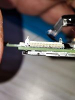
Ouch that seems difficult. Even i have all the tool, but afraid to do it, since i don't have experience on it. Need a broken dummy board to experiment the method and the heat parameter which suited.

The glitch will worked even without the display.
 

cgtchy0412

Well-Known Member
Member
Joined
Apr 26, 2023
Messages
287
Trophies
0
Age
41
XP
436
Country
Indonesia
The issue only happends in sleep mode , when the console is up everything is ok , you put her to sleep and some times wakes up in ofw
That doesnt make sense, unless it crashed in cfw sleep then auto reboot and when glicth doesnt work it goes to ofw.
You need to post video for better undestanding.
 

Site & Scene News

Popular threads in this forum

General chit-chat
Help Users
  • No one is chatting at the moment.
    BakerMan @ BakerMan: (and the joke here is that i misheard pride month as bread month)