Switch OLED B point PROBLEM RP2040

Consoledestroyer

Member
OP
Newcomer
Joined
Sep 7, 2023
Messages
10
Trophies
0
Age
29
XP
66
Country
Poland
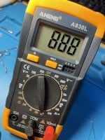
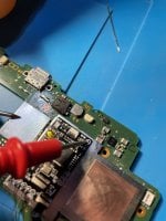
Hello, today i soldered and installed my firs Switch modchip. I measured all the values - A, C, D, 3,3v were fine: 0.500-0.900v. Only B point’s (RST) value was incorrect. I know it should be 0 or 2.9v but in my case it was something like 1.1v. I tried to resolder it but nothing changed so I installed it as it was, set up and tried turn on the console. Unfortunately the console did not started, there was only black screen and chip did’t get any flash light. I heard that something was working inside when I pressed start button- it was silently buzzing until I turned it off by long pressing power button. The situation is very weird for me because the B point shows 0 value on motherboard and 1.1v when it is connected to the chip but it is not all… When I measure value of B point directly on the chip even if it is not connected to the console’s motherboard it shows the same value - 1.1v. I thought it could be caused by wrong soldered cpu flex tape but everything seems good. Outside capacitors gives 0v and inside ones gives something like 13v. insides and outsides cpu capacitors beeps as well when being measured. I have no idea what is going on. I will be very grateful for every response.
Post automatically merged:

There is a possibility that I have done a bad installation. I thought there are the same points for every kind of mod chips for switch Oled and now I see that It may not be true. As you can see with the chip I got a flex tape like that and there is different b point than I can see on YouTube videos. I have done this installation with this YouTube video:
IMG_3288.jpeg
IMG_3287.jpeg
 

Attachments

  • IMG_3285.jpeg
    IMG_3285.jpeg
    1.8 MB · Views: 47
  • IMG_3284.jpeg
    IMG_3284.jpeg
    1.6 MB · Views: 48
Last edited by Consoledestroyer,

bennet321

Active Member
Newcomer
Joined
Apr 6, 2023
Messages
25
Trophies
0
Age
35
XP
128
Country
Australia
Try disconnecting the chip. If the console starts up it is the chip. If not then you may have damaged something on the mainboard. Also shorts on CPU capacitors are normal as they have very low ESR so I would not worry too much about those.
Plus I am not too sure what you mean by a different b point? B should be connected to point b. There are diagrams online that will show what point is b on the mainboard. That point will connect to point b on the tape
 
Last edited by bennet321,

Consoledestroyer

Member
OP
Newcomer
Joined
Sep 7, 2023
Messages
10
Trophies
0
Age
29
XP
66
Country
Poland
Okay I will check it as soon as possible. I am thinking about disconnecting wires from chip and connect them to the flex tape I provided in photo. Is there a possibility that chip need to be connected that way instead like I did?
 

Consoledestroyer

Member
OP
Newcomer
Joined
Sep 7, 2023
Messages
10
Trophies
0
Age
29
XP
66
Country
Poland
It should not really matter. But I did just notice that the GND point is not connected in the photo
I was albo thinking about that but in the video I provided author did not solder it too so I thought it is not a big deal. Interesting thing is why the mod chip is not blinking on any color. I read some posts on Reddit with similar problem when guy had incorrect value on b point and console as well as chip did not respond. B point is very important but it is interesting why chip itself gives any value on the points when wire is not connected. I think it should not be like that but you can change my Mind if I am wrong.
 

bennet321

Active Member
Newcomer
Joined
Apr 6, 2023
Messages
25
Trophies
0
Age
35
XP
128
Country
Australia
I would certainly solder that GND point. It is there for a reason. I don't know about this particular case but I would actually expect a value to be read on the chip, but depending on how the circuit is constructed it may well be normal. Also are you taking your diode readings properly with red probe on GND?
 
  • Like
Reactions: Consoledestroyer

Consoledestroyer

Member
OP
Newcomer
Joined
Sep 7, 2023
Messages
10
Trophies
0
Age
29
XP
66
Country
Poland
I would certainly solder that GND point. It is there for a reason. I don't know about this particular case but I would actually expect a value to be read on the chip, but depending on how the circuit is constructed it may well be normal. Also are you taking your diode readings properly with red probe on GND?
I soldered the ground point and it helped! Everything works excellent now. Thank you for help.
 

Site & Scene News

Popular threads in this forum

General chit-chat
Help Users
  • No one is chatting at the moment.
    K3Nv2 @ K3Nv2: Right onto uremums 3d printed dildo