


https://rentry.org/Getting_StartedWhere can I find a written guide that talks about updating the proper way? Thanks!
Picofly AIO Thread
- Thread starter Adran_Marit
- Start date
- Views 780,126
- Replies 3,575
- Likes 64


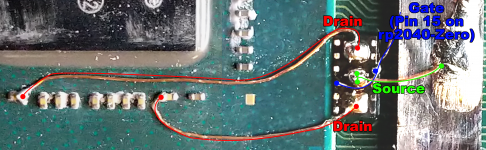
 Hence, the confusion as to why the daughter board was touched at all.
 .
.


Similar threads
Site & Scene News
New Hot Discussed
-
-
10K views
Nintendo announces plans to discontinue Nintendo Switch line in Europe next year, outlines upcoming hardware changes for other devices
Last month we got confirmation of a new model of Switch 2 to better comply with upcoming EU regulations. With the legislation set to come into effect in February of... -
7K views
ROM Hack Ocarina of Time 3D gets huge mod to enable single-screen play
Ocarina of Time is back in style as the upcoming Switch 2 remake looms on the horizon. But what's a fan of the game to do over the next few months? If you've been... -
7K views
A multi-platform port for Pokemon Emerald is in the works, supports Windows, Linux, and Android
Tired of waiting for Game Freak to bring Pokemon Emerald to modern platforms? We've got you covered with a brand new port in the works. Currently available on GitHub... -
6K views
ROM Hack Pokemon Timeless Diamond and Spaceless Pearl released, enhances original Sinnoh releases with quality of life changes and new events
For fans of Sinnoh, the pickings are slim. If you want the best experience you're left deciding between the updated region in Platinum, or the somewhat controversial... -
5K views
Homebrew app PS2 emulator NetherSX2 gets a Switch port
The Switch 2 has been out for a year now, but you shouldn't count the original system out yet! Released a few days ago, popular PS2 emulator NetherSX2 has found its... -
5K views
ROM Hack Better Super Mario Sunshine Online released, adds online co-op and custom hide and seek game mode to play
If you've been waiting for an excuse to replay Super Mario Sunshine and happen to have up to nine friends, do I have some good news for you. Released earlier today... -
5K views
Homebrew app Wii U emulator Cemu gets a homebrew Switch port, Wind Waker HD shown running at full speed
Hot on the heels of their NetherSX2 port, @Nagaa is back with another hugely anticipated release: a Switch port of the popular Wii U emulator Cemu. We've got more... -
4K views
ROM Hack Pokemblem is the best spin off Game Freak never made
The Pokemon series is known for its vast assortment of spin off titles, with the majority being well-received. We've had an assortment of Mystery Dungeon titles, a... -
4K views
Homebrew app The Switch gets 3DS emulation with Dekopon, a new Azahar port
Right on the heels of a NetherSX2 port, the Switch once again proves it's still got some life left in it as 3DS emulation graces the system. Promising mostly... -
4K views
Homebrew app GameCube and Wii emulator Dolphin gets a native Switch port, supports RetroAchievements and loading from USB storage
The golden age of emulation on the Switch continues as a native Dolphin port was released by @Nagaa earlier today. Included in this port, we're looking at cover art...
-
-
-
75 replies
Nintendo announces plans to discontinue Nintendo Switch line in Europe next year, outlines upcoming hardware changes for other devices
Last month we got confirmation of a new model of Switch 2 to better comply with upcoming EU regulations. With the legislation set to come into effect in February of... -
63 replies
ROM Hack Ocarina of Time 3D gets huge mod to enable single-screen play
Ocarina of Time is back in style as the upcoming Switch 2 remake looms on the horizon. But what's a fan of the game to do over the next few months? If you've been... -
57 replies
A multi-platform port for Pokemon Emerald is in the works, supports Windows, Linux, and Android
Tired of waiting for Game Freak to bring Pokemon Emerald to modern platforms? We've got you covered with a brand new port in the works. Currently available on GitHub... -
37 replies
Remasters for Fallout 3 and New Vegas announced, Fallout 5 still in development
Amidst news of layoffs and cancellations in the wake of Xbox's larger changes, Bethesda has today come out with a statement discussing their active projects. In this... -
36 replies
Octopath Traveler and Octopath Traveler II set to launch digitally on Switch 2 today, unclear as to whether an upgrade path will be available
Announced today during the Octopath Traveler 8th Anniversary live stream, it's been confirmed that both the first game and its sequel will be launching on the Switch... -
36 replies
ROM Hack Pokemon Timeless Diamond and Spaceless Pearl released, enhances original Sinnoh releases with quality of life changes and new events
For fans of Sinnoh, the pickings are slim. If you want the best experience you're left deciding between the updated region in Platinum, or the somewhat controversial... -
35 replies
Pokemon Yellow added to first generation recompilation library, voxel mod updated to support "3Dish battles"
It's a good time to be a first generation Pokemon fan. But when was it not a good time to be one? In recent weeks we've seen a native LOVE2D recreation of Pokemon Red... -
32 replies
Monster Hunter Wilds to get permanent price drop from August 4th
In this time of everything costing more a year after it's released, it's nice to see some things sticking to the old ways. Capcom have today announced that the latest... -
24 replies
ROM Hack Better Super Mario Sunshine Online released, adds online co-op and custom hide and seek game mode to play
If you've been waiting for an excuse to replay Super Mario Sunshine and happen to have up to nine friends, do I have some good news for you. Released earlier today... -
21 replies
ROM Hack Pokemblem is the best spin off Game Freak never made
The Pokemon series is known for its vast assortment of spin off titles, with the majority being well-received. We've had an assortment of Mystery Dungeon titles, a...
-


