Hi,Will you be adapting the iPad charge flex punch hole design on your flex?
View attachment 300944
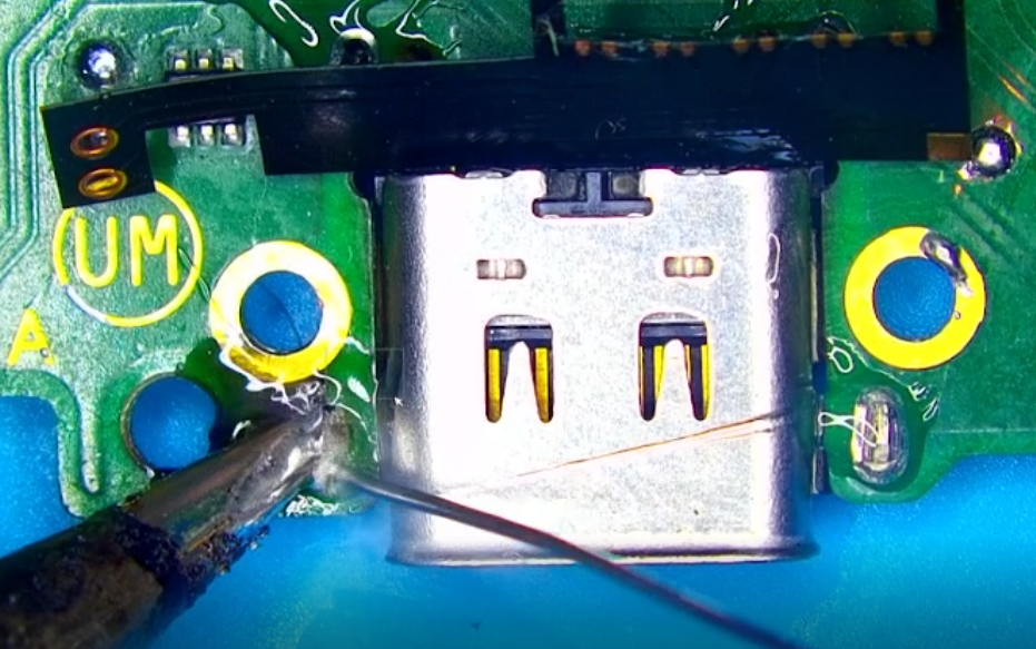
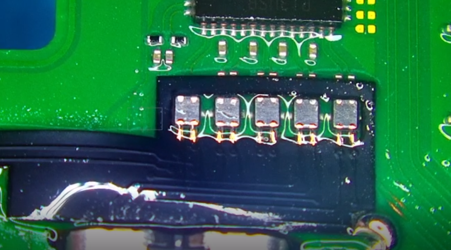
Since the assumption is that the pads on the Nintendo Switch would be torn as shown below, there wouldn't be any pads to solder a punch hole design to. The Nintendo Switch USB C Fix has pads to solder to restore all 24 traces on the Nintendo Switch without the need to run jumper wires. If the iPad flex had one torn trace below, you would need to run a jumper to that flex in order to restore functionality of that ripped trace. If you could explain the reasoning behind the said design we can definitely look into incorporating it.
Thanks