


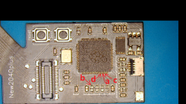
post here detailed pics of your soldering on tegra capsI installed PicoFly (or how they call it, HwFly RP2040) with FW2.73 using flex cables in my Switch Lite. It works, but the time to glitch it varies a lot - from 3 seconds up to 90 seconds. It glitches every time and boots without any issues, the only issue is the time to do it.
A: 0.712
B: My multimeter can't measure it, should be good
C: 0.712
D: 0.712
CPU: 0.14 on both sides
This is the second Switch Lite I installed a PicoFly modchip in and it was the same case with the first one. I tried 3 PicoFly modchips, tried reworking the CPU solder joints, but nothing changed.
Any ideas what to try next or what to check? Or I should consider this normal behavior for this Switch and use it as is?
You are using an out of date browser. It may not display this or other websites correctly.
You should upgrade or use an alternative browser.
You should upgrade or use an alternative browser.


Glitch times is chip dependent, you cannot change unless you use a different eMMC. You can try a different firmware but I doubt anything would change.I installed PicoFly (or how they call it, HwFly RP2040) with FW2.73 using flex cables in my Switch Lite. It works, but the time to glitch it varies a lot - from 3 seconds up to 90 seconds. It glitches every time and boots without any issues, the only issue is the time to do it.
A: 0.712
B: My multimeter can't measure it, should be good
C: 0.712
D: 0.712
CPU: 0.14 on both sides
This is the second Switch Lite I installed a PicoFly modchip in and it was the same case with the first one. I tried 3 PicoFly modchips, tried reworking the CPU solder joints, but nothing changed.
Any ideas what to try next or what to check? Or I should consider this normal behavior for this Switch and use it as is?
Glitch times is chip dependent, you cannot change unless you use a different eMMC. You can try a different firmware but I doubt anything would change.
Thanks @Hassal . Can you recommend some dependable versions of FW that I can try?
I believe these chips come with 2.67 stock so you can try that. I don't think you could flash this with other firmware used by HWFLY.Thanks @Hassal . Can you recommend some dependable versions of FW that I can try?
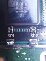
improve that, that´s the cause of your long glitchings time
you need to do it this way in order to have instant boot. A good ground points also helps. Clean as much as possible
Best regards
Attachments
Last edited by one-armed,

I installed PicoFly (or how they call it, HwFly RP2040) with FW2.73 using flex cables in my Switch Lite. It works, but the time to glitch it varies a lot - from 3 seconds up to 90 seconds. It glitches every time and boots without any issues, the only issue is the time to do it.
A: 0.712
B: My multimeter can't measure it, should be good
C: 0.712
D: 0.712
CPU: 0.14 on both sides
This is the second Switch Lite I installed a PicoFly modchip in and it was the same case with the first one. I tried 3 PicoFly modchips, tried reworking the CPU solder joints, but nothing changed.
Any ideas what to try next or what to check? Or I should consider this normal behavior for this Switch and use it as is?
Same issue here on switch lite, used a hwfly rp2040 based, shipped already flashed.
When it exceeds 20seconds of glitching times, even if it finally succeed, switch won't boot.
I have this behaviour 1 time every 25 times.
Post automatically merged:
improve that, that´s the cause of your long glitchings time
you need to do it this way in order to have instant boot. A good ground points also helps. Clean as much as possible
Best regards
Points are connected well in his case. Contact is made, multimeter says it, period.
Quality of solder can impact longevity of the soldering but not glitching time


Points are connected well in his case. Contact is made, multimeter says it, period.
Quality of solder can impact longevity of the soldering but not glitching time
It can effect glitching time, if the contact is too small.
This sentence you wrote can´t be more unexact for the purpose we have here.Points are connected well in his case. Contact is made, multimeter says it, period.
Quality of solder can impact longevity of the soldering but not glitching time
I highly recomend you to read and also understand how the glich attack is achieved on tegra x1 before advise each other here.
Okay,This sentence you wrote can´t be more unexact for the purpose we have here.
I highly recomend you to read and also understand how the glich attack is achieved on tegra x1 before advise each other here.
Do you have any link so i can learn more about the voltage glitch on x1 ?

https://media.ccc.de/v/c4.openchaos.2018.06.glitching-the-switchOkay,
Do you have any link so i can learn more about the voltage glitch on x1 ?
I really like this video
Best regards
Hi! I have recently installed one of these RP2040 HWFly Core boards on a Mariko V2 with Samsung EMMC.
https://a.aliexpress.com/_EuMhJjZ
It came without preloaded FW, installed 2.73 everything went fine, good solder work and am getting insta boot all times.
Hekate just loads fine but got the EMMC on slow mode while doing the NAND bak which completed successfully two times, but took longer.
It boots with EMMC @400Mhz but after some reads goes into slow mode (backups / benchmark)
Hekate EMMC screens tells me init error counter as 2. No R/W erros and the EMMC goes into slow mode.
Was able to boot HOS just fine but games with the updates installed on the EMMC are crashing almost always.
Do you have any ideas? Defective chip? Badly installed EMMC module on the Pico board?
Am thinking into buying an SX based HWFly which are still available on AliExpress.
Thanks!

Since these board are clones of the original work that started here in GBA, anything is possible. They just want to be the first in the market and don't give a shit when they customers (like you get into trouble) and thats why we always suggest that for this mod you go with the original supported boards (listed in the guide)Hi! I have recently installed one of these RP2040 HWFly Core boards on a Mariko V2 with Samsung EMMC.
https://a.aliexpress.com/_EuMhJjZ
It came without preloaded FW, installed 2.73 everything went fine, good solder work and am getting insta boot all times.
Hekate just loads fine but got the EMMC on slow mode while doing the NAND bak which completed successfully two times, but took longer.
It boots with EMMC @400Mhz but after some reads goes into slow mode (backups / benchmark)
Hekate EMMC screens tells me init error counter as 2. No R/W erros and the EMMC goes into slow mode.
Was able to boot HOS just fine but games with the updates installed on the EMMC are crashing almost always.
Do you have any ideas? Defective chip? Badly installed EMMC module on the Pico board?
Am thinking into buying an SX based HWFly which are still available on AliExpress.
Thanks!
That being said, it seems that your issue is related to the resistors used in this board.
You should try to solder another 47ohm resistor to the dat0 line and it should be fine.
Thanks, do you know which size are they used by eye seems like 0402 resistors.Since these board are clones of the original work that started here in GBA, anything is possible. They just want to be the first in the market and don't give a shit when they customers (like you get into trouble) and thats why we always suggest that for this mod you go with the original supported boards (listed in the guide)
That being said, it seems that your issue is related to the resistors used in this board.
You should try to solder another 47ohm resistor to the dat0 line and it should be fine.
I guess I'll replace the HWFly board one with a 100Ohm one and test.
Should I change the DAT0 one only or the CMD aswell?
Thank you very much for your support.
I have no idea since I have no clue about the board you are using but you can just eyeball it and as long as it sits in place without touching anything around it should be fine. I would just do dat0, but if you are ok with soldering those little fckrs you could do cmd as well. You are welcome.Thanks, do you know which size are they used by eye seems like 0402 resistors.
I guess I'll replace the HWFly board one with a 100Ohm one and test.
Should I change the DAT0 one only or the CMD aswell?
Thank you very much for your support.

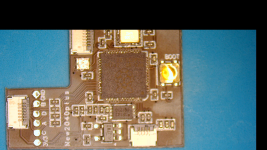
Ok so in order to help some guys that have problems with those clones. Today arrived some of the new ones called rp2040 PLUS  .
.
The values of the reistors are these :
oled old
point a cmd 47 ohms
point d clk 47 ohms
point c dat0 47 ohms
point b no resistor
oled new
point a cmd 47ohms
point d clk 47 ohms
point c dat0 240 ohms
point b no resistor
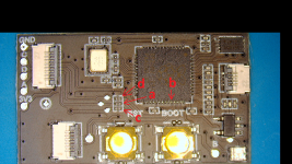
v1-v2
point a 50 ohms
point d 50 ohms
point c 330 ohms
point b 50 ohms
lite
point a 50 ohms
point d 50 ohms
point c 240 ohms
point b 50 ohms
instinct-v6
point a 240 ohms
point d 240 ohms
point c 240 ohms
point b 33 kiloohms
From the measurements above we can see:
1) The oled chips dont have resistors at rst point b which i think is good. But we can see that lite and v1-v2 models use 50 ohm resistors at point b which is not recommended.
2) On newer PLUS chips the main difference is the addition of 240 ohm resistors, instead of 47-50 ohms, at c dat0 points.
I dont know if they are influenced from instinct-nx chips which use 240 ohms at all a,d and c points. This also doesnt make a lot of sense since the recommendation is to add 100 ohm resistors at point c dat0.
3)for some reason the v1-v2 clone uses 330 ohms at point c. Even more than 240 ohms which are used at oled and lite rp 2040 clone boards.
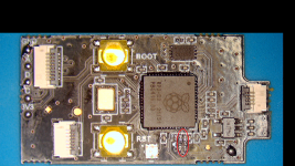
First of all check if you have slow emmc errors after the installation. If yes then proceed with the following:
On old oled boards add 2 more 0201 47 ohm resistor at point c and point a as you can see in my picture (or simply replace them with 100 ohm resistors) . First cut the traces and then add the 47 resistors if you dont replace with 100 ohm.
On new oled models replace the 0201 resistors of point a and c with 100 ohm resistors.
On v1-v2 board replace point a and c with 100 ohm 0402 resistors and if it still doesnt work remove the 50ohm point b resistor and bridge the points.
On lite board
replace point a and c with 100 ohm 0201 resistors and if it still doesnt work remove the 50ohm point b resistor and bridge the points.
.The values of the reistors are these :
oled old
point a cmd 47 ohms
point d clk 47 ohms
point c dat0 47 ohms
point b no resistor
oled new
point a cmd 47ohms
point d clk 47 ohms
point c dat0 240 ohms
point b no resistor
v1-v2
point a 50 ohms
point d 50 ohms
point c 330 ohms
point b 50 ohms
lite
point a 50 ohms
point d 50 ohms
point c 240 ohms
point b 50 ohms
instinct-v6
point a 240 ohms
point d 240 ohms
point c 240 ohms
point b 33 kiloohms
From the measurements above we can see:
1) The oled chips dont have resistors at rst point b which i think is good. But we can see that lite and v1-v2 models use 50 ohm resistors at point b which is not recommended.
2) On newer PLUS chips the main difference is the addition of 240 ohm resistors, instead of 47-50 ohms, at c dat0 points.
I dont know if they are influenced from instinct-nx chips which use 240 ohms at all a,d and c points. This also doesnt make a lot of sense since the recommendation is to add 100 ohm resistors at point c dat0.
3)for some reason the v1-v2 clone uses 330 ohms at point c. Even more than 240 ohms which are used at oled and lite rp 2040 clone boards.
First of all check if you have slow emmc errors after the installation. If yes then proceed with the following:
On old oled boards add 2 more 0201 47 ohm resistor at point c and point a as you can see in my picture (or simply replace them with 100 ohm resistors) . First cut the traces and then add the 47 resistors if you dont replace with 100 ohm.
On new oled models replace the 0201 resistors of point a and c with 100 ohm resistors.
On v1-v2 board replace point a and c with 100 ohm 0402 resistors and if it still doesnt work remove the 50ohm point b resistor and bridge the points.
On lite board
replace point a and c with 100 ohm 0201 resistors and if it still doesnt work remove the 50ohm point b resistor and bridge the points.
Attachments

After reading your post, I think we should adopt/test with these resistence values based in the switch version, rather than changing them on the ribbons. I suspect that the "official"(100ohm) method tried to use universal resistence values which might not be optimal for every switch version.Ok so in order to help some guys that have problems with those clones. Today arrived some of the new ones called rp2040 PLUS
The values of the reistors are these :
oled old
point a cmd 47 ohms
point d clk 47 ohms
point c dat0 47 ohms
point b no resistor
oled new
point a cmd 47ohms
point d clk 47 ohms
point c dat0 240 ohms
point b no resistor
v1-v2
point a 50 ohms
point d 50 ohms
point c 330 ohms
point b 50 ohms
lite
point a 50 ohms
point d 50 ohms
point c 240 ohms
point b 50 ohms
instinct-v6
point a 240 ohms
point d 240 ohms
point c 240 ohms
point b 33 kiloohms
From the measurements above we can see:
1) The oled chips dont have resistors at rst point b which i think is good. But we can see that lite and v1-v2 models use 50 ohm resistors at point b which is not recommended.
2) On newer PLUS chips the main difference is the addition of 240 ohm resistors, instead of 47-50 ohms, at c dat0 points.
I dont know if they are influenced from instinct-nx chips which use 240 ohms at all a,d and c points. This also doesnt make a lot of sense since the recommendation is to add 100 ohm resistors at point c dat0.
3)for some reason the v1-v2 clone uses 330 ohms at point c. Even more than 240 ohms which are used at oled and lite rp 2040 clone boards.
First of all check if you have slow emmc errors after the installation. If yes then proceed with the following:
On old oled boards add 2 more 0201 47 ohm resistor at point c and point a as you can see in my picture (or simply replace them with 100 ohm resistors) . First cut the traces and then add the 47 resistors if you dont replace with 100 ohm.
On new oled models replace the 0201 resistors of point a and c with 100 ohm resistors.
On v1-v2 board replace point a and c with 100 ohm 0402 resistors and if it still doesnt work remove the 50ohm point b resistor and bridge the points.
On lite board
replace point a and c with 100 ohm 0201 resistors and if it still doesnt work remove the 50ohm point b resistor and bridge the points.
@abal1000x what do you think?
On second thought, if it works there might be no need to change the values. I was just hoping to eliminate some of the more common and seemingly random issues encountered until now. This is way over my head anyway
")
Last edited by twins333,

I think the new hwfly is already good.After reading your post, I think we should adopt/test with these resistence values based in the switch version, rather than changing them on the ribbons. I suspect that the "official"(100ohm) method tried to use universal resistence values which might not be optimal for every switch version.
@abal1000x what do you think?
On second thought, if it works there might be no need to change the values. I was just hoping to eliminate some of the more common and seemingly random issues encountered until now. This is way over my head anyway
Adding the dat0 resistor is a good one.
Its not always 100 ohms. Its just that 100ohms is the most people used, to fix the 'slow emmc' issue.
And if its tested by most, then its the best.
I myself have made an experiment until 1kOhms, and it seems works.
Adding the resistor to the nvidia reset line, seems 'not wise' decision.
i don't see anyone do it, so it might triggered an unknown issue.
'If it aint broken then dont fix'
Similar threads
- Replies
- 11
- Views
- 2K
- Replies
- 16
- Views
- 3K
- Replies
- 3
- Views
- 1K
Site & Scene News
New Hot Discussed
-
-
26K views
Wii U and 3DS online services shutting down today, but Pretendo is here to save the day
Today, April 8th, 2024, at 4PM PT, marks the day in which Nintendo permanently ends support for both the 3DS and the Wii U online services, which include co-op play...by ShadowOne333 179 -
23K views
Nintendo Switch firmware update 18.0.1 has been released
A new Nintendo Switch firmware update is here. System software version 18.0.1 has been released. This update offers the typical stability features as all other... -
19K views
The first retro emulator hits Apple's App Store, but you should probably avoid it
With Apple having recently updated their guidelines for the App Store, iOS users have been left to speculate on specific wording and whether retro emulators as we... -
18K views
Delta emulator now available on the App Store for iOS
The time has finally come, and after many, many years (if not decades) of Apple users having to side load emulator apps into their iOS devices through unofficial...by ShadowOne333 96 -
17K views
TheFloW releases new PPPwn kernel exploit for PS4, works on firmware 11.00
TheFlow has done it again--a new kernel exploit has been released for PlayStation 4 consoles. This latest exploit is called PPPwn, and works on PlayStation 4 systems... -
14K views
Nintendo takes down Gmod content from Steam's Workshop
Nintendo might just as well be a law firm more than a videogame company at this point in time, since they have yet again issued their now almost trademarked usual...by ShadowOne333 116 -
13K views
A prototype of the original "The Legend of Zelda" for NES has been found and preserved
Another video game prototype has been found and preserved, and this time, it's none other than the game that spawned an entire franchise beloved by many, the very...by ShadowOne333 31 -
11K views
Anbernic reveals specs details of pocket-sized RG28XX retro handheld
Anbernic is back with yet another retro handheld device. The upcoming RG28XX is another console sporting the quad-core H700 chip of the company's recent RG35XX 2024... -
10K views
Nintendo officially confirms Switch successor console, announces Nintendo Direct for next month
While rumors had been floating about rampantly as to the future plans of Nintendo, the President of the company, Shuntaro Furukawa, made a brief statement confirming... -
10K views
Nintendo Switch Online adds two more Nintendo 64 titles to its classic library
Two classic titles join the Nintendo Switch Online Expansion Pack game lineup. Available starting April 24th will be the motorcycle racing game Extreme G and another...
-
-
-
182 replies
Name the Switch successor: what should Nintendo call its new console?
Nintendo has officially announced that a successor to the beloved Switch console is on the horizon. As we eagerly anticipate what innovations this new device will...by Costello -
179 replies
Wii U and 3DS online services shutting down today, but Pretendo is here to save the day
Today, April 8th, 2024, at 4PM PT, marks the day in which Nintendo permanently ends support for both the 3DS and the Wii U online services, which include co-op play...by ShadowOne333 -
170 replies
Nintendo officially confirms Switch successor console, announces Nintendo Direct for next month
While rumors had been floating about rampantly as to the future plans of Nintendo, the President of the company, Shuntaro Furukawa, made a brief statement confirming...by Chary -
116 replies
Nintendo takes down Gmod content from Steam's Workshop
Nintendo might just as well be a law firm more than a videogame company at this point in time, since they have yet again issued their now almost trademarked usual...by ShadowOne333 -
97 replies
The first retro emulator hits Apple's App Store, but you should probably avoid it
With Apple having recently updated their guidelines for the App Store, iOS users have been left to speculate on specific wording and whether retro emulators as we...by Scarlet -
96 replies
Delta emulator now available on the App Store for iOS
The time has finally come, and after many, many years (if not decades) of Apple users having to side load emulator apps into their iOS devices through unofficial...by ShadowOne333 -
82 replies
Nintendo Switch firmware update 18.0.1 has been released
A new Nintendo Switch firmware update is here. System software version 18.0.1 has been released. This update offers the typical stability features as all other...by Chary -
80 replies
TheFloW releases new PPPwn kernel exploit for PS4, works on firmware 11.00
TheFlow has done it again--a new kernel exploit has been released for PlayStation 4 consoles. This latest exploit is called PPPwn, and works on PlayStation 4 systems...by Chary -
70 replies
DOOM has been ported to the retro game console in Persona 5 Royal
DOOM is well-known for being ported to basically every device with some kind of input, and that list now includes the old retro game console in Persona 5 Royal...by relauby -
61 replies
Microsoft is closing down several gaming studios, including Tango Gameworks and Arkane Austin
The number of layoffs and cuts in the videogame industry sadly continue to grow, with the latest huge layoffs coming from Microsoft, due to what MIcrosoft calls a...by ShadowOne333
-