Help with the Instinc v6 post-installation

nalex7752

Active Member
OP
Newcomer
Joined
Jul 27, 2019
Messages
33
Trophies
0
Age
25
XP
211
Country
Italy
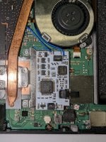
Hi all, i got this Oled with the instinct v6 installed but i cant recognize the led sequence. tested all the points, the readings are: 3.3v .718 - D .632 - A .549 - C .553 - On the D point i cant get a reading, but i read that some multimeter (like mine cheap AF) cant get a good measurement, i got continuity and if i switch to ohm-mode i got around 60k ohm and the value keep increasing. Other than that, i couldnt recognize the led color sequence on the mochip bc im colorblind :/ the color sequence seems 2x red -> 2x green -> 2x purple -> solid white and then boots to ofw. What could it be?

Thanks all!

side note: the console has not been used for a year or so and i cant check whats the FW because there's a pending update. Also, do i need to update the firmware on the chip?
Post automatically merged:

EDIT: errata corrige "On the D point i cant get a reading..." its the B point actually, my bad
 

Attachments

  • PXL_20231215_083948447 (1).mp4
    31.1 MB
Last edited by nalex7752,

nalex7752

Active Member
OP
Newcomer
Joined
Jul 27, 2019
Messages
33
Trophies
0
Age
25
XP
211
Country
Italy
Did you do the install yourself, can you provide pics if you did?
Yep, I did the installation
I'm not at home at the moment and I only got this image.
 

Attachments

  • PXL_20231215_135813258.RAW-01.COVER.jpg
    PXL_20231215_135813258.RAW-01.COVER.jpg
    2.8 MB · Views: 20

HawaiianInTown

Friendly Neighborhood Hawaiian
Member
Joined
Dec 1, 2023
Messages
215
Trophies
0
XP
365
Country
United States
Loosely based on the soldering you've done on the modchip, you could use more flux and a tad more solder too, also be sure to clean flux everywhere after if you haven't.

EDT: It's a decent install, I'd suggest retouching the points on the chip... not sure about the points across the mobo without pics
 

nalex7752

Active Member
OP
Newcomer
Joined
Jul 27, 2019
Messages
33
Trophies
0
Age
25
XP
211
Country
Italy
Loosely based on the soldering you've done on the modchip, you could use more flux and a tad more solder too, also be sure to clean flux everywhere after if you haven't.
I read that this modchip quality isnt that great and to pay attention to not add to much solder on the chip pads as it could easily short on the ground of the chip.
Btw thanks, ill redo all of my soldering.
 
  • Like
Reactions: HawaiianInTown

HawaiianInTown

Friendly Neighborhood Hawaiian
Member
Joined
Dec 1, 2023
Messages
215
Trophies
0
XP
365
Country
United States
Got it, sorry I'm not aware of that info. I don't own the OLED version, based off of the soldering. I'll keep that info in mind when I get the OLED version. As far as LED diagnosis, I've never seen a modchip do that, did it have preinstalled UF2? Do you know what version it has?
 

nalex7752

Active Member
OP
Newcomer
Joined
Jul 27, 2019
Messages
33
Trophies
0
Age
25
XP
211
Country
Italy
Got it, sorry I'm not aware of that info. I don't own the OLED version, based off of the soldering. I'll keep that info in mind when I get the OLED version. As far as LED diagnosis, I've never seen a modchip do that, did it have preinstalled UF2? Do you know what version it has?
I got the chip off AliExpress, but I don't know if it's preflashed. I found a guide here for flashing, which involves soldering directly onto the chip. However, I have a microUSB breakout that I believe could be used for updating. Is it as simple as plugging in the 'dongle' and dragging and dropping the UF2 file? Also, where should I connect the microUSB? There are two empty connectors on the chip...
 

HawaiianInTown

Friendly Neighborhood Hawaiian
Member
Joined
Dec 1, 2023
Messages
215
Trophies
0
XP
365
Country
United States
I'm not sure my guy, I've never installed the OLED chip. Gonna have to wait for someone with OLED chip experience. I did notice, is GND not connected on these installs?
 

Hayato213

Newcomer
Member
Joined
Dec 26, 2015
Messages
19,952
Trophies
1
XP
20,987
Country
United States
I got the chip off AliExpress, but I don't know if it's preflashed. I found a guide here for flashing, which involves soldering directly onto the chip. However, I have a microUSB breakout that I believe could be used for updating. Is it as simple as plugging in the 'dongle' and dragging and dropping the UF2 file? Also, where should I connect the microUSB? There are two empty connectors on the chip...

Sound like point B problem

1702650674574.png
 
  • Like
Reactions: HawaiianInTown

nalex7752

Active Member
OP
Newcomer
Joined
Jul 27, 2019
Messages
33
Trophies
0
Age
25
XP
211
Country
Italy
I am just going by what you said, but looking at your soldering, it ain't perfect, it can explain why it isn't working.
Yeah, totally!
I mean, im not new to soldering but its my first time doing something on a switch so could absolutely be!
Anyway, thanks again, ill check another time my soldering and ill post it back if i find any other problem.
But, do i need to update the firmware on the chip? Is there a guide i can follow to?
Post automatically merged:

UPDATE: I think that the trouble that I'm having starts from the B point on the instinct. I think I've exceeded a bit the solder pad on the chip, could it be?

Back of the motherboard, B point: https://ibb.co/LJyRhJg

B point on the chip (red circle is the actual solder pad?): https://ibb.co/hWdLZ3f - https://ibb.co/vzBYPrd
 
Last edited by nalex7752,

Site & Scene News

Popular threads in this forum

General chit-chat
Help Users
    K3Nv2 @ K3Nv2: Oh boy psi posted a ltt video +1