


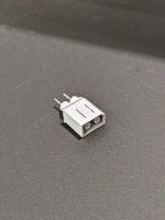
I made a dongle the other day and it seems to be able to charge 2x wiimotes and 1x gamepad while running Zelda BOTW. I used this decoy module (which can change voltages with a solder bridge) and a WiiU power plug . A 3d-printed little face plate and I'd look decent.
You are using an out of date browser. It may not display this or other websites correctly.
You should upgrade or use an alternative browser.
You should upgrade or use an alternative browser.
Hardware PD4Wii, PD4WiiU - A DIY USB-C replacement for the Wii and Wii U power adapter
- Thread starter EnterpriseFreak
- Start date
- Views 14,425
- Replies 48
- Likes 16
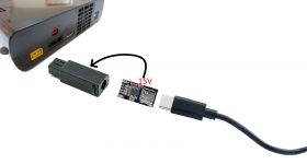
I made a dongle the other day and it seems to be able to charge 2x wiimotes and 1x gamepad while running Zelda BOTW. I used this decoy module (which can change voltages with a solder bridge) and a WiiU power plug . A 3d-printed little face plate and I'd look decent.
Very nice find that power plug. Here's a fun fact: the very first version of PD4WiiU used that exact same decoy but then I ditched it in favor of the PDC004 due to it's smaller footprint. As for the total power consumption: Assuming you haven't made any mods to bypass the 500mA limit on the USB ports that should put you at around 37 - 40 Watt power consumption. 30 - 35W for the console itself (depends on if you're playing from a Disc or not) and then 2.5W per USB device attached to the console.
Anyway, I think I should talk about the progress V2 of PD4Wii(U) while I'm at it. The design is like 99.99999% complete now but I'm experimenting with different materials for the print right now, that's why I haven't updated the OP yet. I've been using PLA so far but I have concern about it being too fragile for the part that goes into the port of the console. I've got a spool of PETG filament yesterday and actually wanted to do a test print then but guess what... A certain someone broke the hotend of his printer while installing a titanium heatbreak... If nothing changes I should have a new hotend by tomorrow and then I can finally test how viable PETG would be for the connector. Sorry for the wait!
Very nice find that power plug. Here's a fun fact: the very first version of PD4WiiU used that exact same decoy but then I ditched it in favor of the PDC004 due to it's smaller footprint. As for the total power consumption: Assuming you haven't made any mods to bypass the 500mA limit on the USB ports that should put you at around 37 - 40 Watt power consumption. 30 - 35W for the console itself (depends on if you're playing from a Disc or not) and then 2.5W per USB device attached to the console.
I actually have made the bypass mod to the back ports as it wouldn't charge all devices correctly before. I'm thinking of doing it for the front USBs as well so that module seem to let it draw pass 3a @15v, I should actually confirm this with an wall power meter.
The PDC004 would be perfect for the power plug I linked as you prob wouldn't need to cut the any of the PCB, maybe even keep the clips. I'm making one version with the PDC004 as well. All you'd need is a nice front plate for the port itself.
Semi-final update. Finally fixed my printer yesterday and did some test prints of the plug using PETG instead of PLA. Worked out just as I wanted it, it's much stronger now which for obvious reasons that's great. Will probably rework the OP today or tomorrow. Just have to make pictures of the assembly process now and then it's time to rewrite everything.
Aaand it's done. Enjoy. Complete with images and everything.
Post automatically merged:
I'd love to see such guide!
Aaand it's done. Enjoy. Complete with images and everything.
Last edited by EnterpriseFreak,

Hey Im building one, thanks for the guide and models! Getting it printed from a service ($20 total from xometry)
Any recommendations for the cheapest small USB-C PD charging block for this?
I don't think any do 12V @ 5A which would be the match to the OEM brick.
Thanks.
Any recommendations for the cheapest small USB-C PD charging block for this?
I don't think any do 12V @ 5A which would be the match to the OEM brick.
Thanks.

Hey Im building one, thanks for the guide and models! Getting it printed from a service ($20 total from xometry)
Any recommendations for the cheapest small USB-C PD charging block for this?
I don't think any do 12V @ 5A which would be the match to the OEM brick.
Thanks.
Don't really have a recommendation for a charge brick. Even launch day Wiis run fine with 3A so you don't have to go out of your way to find a QC Charger that supports 12V @ 5A.
I jsut found this Thread today but holy F! I am so gonna do that once my 3D Printer arrives!
Will there also be an option for the Wii U Gamepad?
I really don't think I'll be creating a dongle for the Gamepad anytime soon especially since I already modded mine to have a USB-C port over a year ago. Here's a link to a thread I made about that mod back then: https://gbatemp.net/threads/just-added-usb-c-to-my-gamepad.607238/
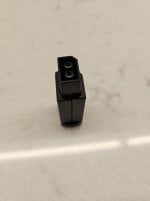
I got a batch of snap together plugs where the inner power connection looks like the attached photo. Would anyone have any tips or suggestions on how to solder it to my power wires? It seems like soldering a wire to a pin like this might not give a very strong connection, and I also melted the plastic housing somewhat on my first attempt
Attachments
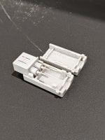
Hi! Sorry for the late reply, I was busy with things. First off try to use solder that melts at a low temperature (there's some that claim to melt at a temperature of about 80 °C which would be below the melting point of ABS plastic) and use a soldering iron which allows you to control the temperature too. Strip a good bit of the wire (from looking at the picture I'd assume 2 - 3mm maybe) and push the stripped wire into the grove, then fill up the grove with solder so that the contacts and the wire have a lot of surface area connecting them.I got a batch of snap together plugs where the inner power connection looks like the attached photo. Would anyone have any tips or suggestions on how to solder it to my power wires? It seems like soldering a wire to a pin like this might not give a very strong connection, and I also melted the plastic housing somewhat on my first attempt
Attachments
oh you're supposed to get all the way in there! That helps a lot I'll try again, thanks!Hi! Sorry for the late reply, I was busy with things. First off try to use solder that melts at a low temperature (there's some that claim to melt at a temperature of about 80 °C which would be below the melting point of ABS plastic) and use a soldering iron which allows you to control the temperature too. Strip a good bit of the wire (from looking at the picture I'd assume 2 - 3mm maybe) and push the stripped wire into the grove, then fill up the grove with solder so that the contacts and the wire have a lot of surface area connecting them.
- Joined
- Jul 23, 2018
- Messages
- 6,060
- Trophies
- 1
- Age
- 29
- Location
- Lampukistan
- Website
- hmpg.net
- XP
- 6,173
- Country

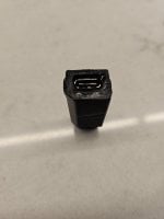
I do a project on my Wii atm and soldered out the power connector (because of the project
") ).
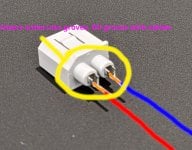
).Could it be that the layout in your picture is wrong? The Wii connector is the Wii U connector and the Wii U connector fits the Wii. If I have made a mistake in my thinking...please ignore it. I just have the connector in my hand. See picture.
Attachments
I do a project on my Wii atm and soldered out the power connector (because of the project
Could it be that the layout in your picture is wrong? The Wii connector is the Wii U connector and the Wii U connector fits the Wii. If I have made a mistake in my thinking...please ignore it. I just have the connector in my hand. See picture.
The picture represents the male connector (the one on the PSU itself). It would be wrong from your point of view because you're looking at the female connector. I've attached a picture of the "official" pinout found on the EUR power brick which shows the same layout I've used.
Attachments

Can you give a link for the ZYPDH ?
Can you give the link for the ZYPDH ?
Post automatically merged:
Can you give the link for the ZYPDH ?
Post automatically merged:
where did you buy this ?I got a batch of snap together plugs where the inner power connection looks like the attached photo. Would anyone have any tips or suggestions on how to solder it to my power wires? It seems like soldering a wire to a pin like this might not give a very strong connection, and I also melted the plastic housing somewhat on my first attempt
Last edited by gamerabbit,
- Joined
- Jul 23, 2018
- Messages
- 6,060
- Trophies
- 1
- Age
- 29
- Location
- Lampukistan
- Website
- hmpg.net
- XP
- 6,173
- Country
Any decoy shaped like this should work. Amazon has a lot of them.
this is better than the ZYPDH ?
because i want to plus any powers supply that can hendel 15-20 v
Post automatically merged:
and that one 100W 5A USB Type-C Decoy PD 2.0 3.0 TO 5V 9V 12V 15V 20V DC Trigger Adapter Module QC4 QC5 Charge Charging Notebook
In my case I went for a decoy that's PD and QC compatible, the ZYPDH. It has the following specs: 100W 5A USB Type-C Decoy PD 2.0 3.0 TO 5V 9V 12V 15V 20V DC Trigger Adapter Module QC4 QC5 Charge Charging Notebook
Can't post links, look it up on Ali
Soldered the Wii U connector to the decoy, used the charger and USB-C cable from my Xiaomi 11T that's QC3 and voilá... The charger can provide up to 67W and the cable is rated for 6A, although the same cable for some reason can't provide 12v, it provides 9 and 15. For that reason, for the consoles that need 12v (like the GC and Wii), I used a Switch Pro Controller USB cable than CAN provide 12v with the same charger.
The PD protocol seems to be more limited than QC.
Ended up making a bunch of those adapters for my consoles, I been using them for 1-2 monts without any issues.
- Joined
- Jul 23, 2018
- Messages
- 6,060
- Trophies
- 1
- Age
- 29
- Location
- Lampukistan
- Website
- hmpg.net
- XP
- 6,173
- Country
Electricity flows through the devices...I don't know how to answer your question "better". The current cannot flow better through one device than through the other. And if you had clicked on my link, your question would answer itself. There are different modules. 9v, 12v, 15v and 20v. For Wii you need 12v and for Wii u 15v.this is better than the ZYPDH ?
because i want to plus any powers supply that can hendel 15-20 v
i mean more for the protocolElectricity flows through the devices...I don't know how to answer your question "better". The current cannot flow better through one device than through the other. And if you had clicked on my link, your question would answer itself. There are different modules. 9v, 12v, 15v and 20v. For Wii you need 12v and for Wii u 15v.
like pd or qc
- Joined
- Jul 23, 2018
- Messages
- 6,060
- Trophies
- 1
- Age
- 29
- Location
- Lampukistan
- Website
- hmpg.net
- XP
- 6,173
- Country
Depending on the parts you use to build one, chargers using USB-PD, Qualcomm QC, or ones compliant with both protocols can be used.i mean more for the protocol
like pd or qc
does an iphone charger work ?
or a school laptop power supply (with usb c) can hendel 20v at 1.5 a or 15v at 2 a ?
and 12v at 2.5 a
or a school laptop power supply (with usb c) can hendel 20v at 1.5 a or 15v at 2 a ?
Post automatically merged:
and 12v at 2.5 a
Post automatically merged:
which is the bestDepending on the parts you use to build one, chargers using USB-PD, Qualcomm QC, or ones compliant with both protocols can be used.
Last edited by gamerabbit,
Similar threads
- Replies
- 5
- Views
- 532
- Replies
- 11
- Views
- 1K
- Replies
- 49
- Views
- 5K
- Replies
- 21
- Views
- 4K
Site & Scene News
New Hot Discussed
-
-
27K views
Atmosphere CFW for Switch updated to pre-release version 1.7.0, adds support for firmware 18.0.0
After a couple days of Nintendo releasing their 18.0.0 firmware update, @SciresM releases a brand new update to his Atmosphere NX custom firmware for the Nintendo...by ShadowOne333 107 -
21K views
Wii U and 3DS online services shutting down today, but Pretendo is here to save the day
Today, April 8th, 2024, at 4PM PT, marks the day in which Nintendo permanently ends support for both the 3DS and the Wii U online services, which include co-op play...by ShadowOne333 179 -
17K views
GBAtemp Exclusive Introducing tempBOT AI - your new virtual GBAtemp companion and aide (April Fools)
Hello, GBAtemp members! After a prolonged absence, I am delighted to announce my return and upgraded form to you today... Introducing tempBOT AI 🤖 As the embodiment... -
14K views
The first retro emulator hits Apple's App Store, but you should probably avoid it
With Apple having recently updated their guidelines for the App Store, iOS users have been left to speculate on specific wording and whether retro emulators as we... -
13K views
Delta emulator now available on the App Store for iOS
The time has finally come, and after many, many years (if not decades) of Apple users having to side load emulator apps into their iOS devices through unofficial...by ShadowOne333 96 -
13K views
MisterFPGA has been updated to include an official release for its Nintendo 64 core
The highly popular and accurate FPGA hardware, MisterFGPA, has received today a brand new update with a long-awaited feature, or rather, a new core for hardcore...by ShadowOne333 54 -
12K views
Nintendo Switch firmware update 18.0.1 has been released
A new Nintendo Switch firmware update is here. System software version 18.0.1 has been released. This update offers the typical stability features as all other... -
11K views
"TMNT: The Hyperstone Heist" for the SEGA Genesis / Mega Drive gets a brand new DX romhack with new features
The romhacking community is always a source for new ways to play retro games, from completely new levels or stages, characters, quality of life improvements, to flat...by ShadowOne333 36 -
9K views
"Sonic 3" movie has wrapped production & Knuckles series gets its official poster
Quite a bit of news have unfolded in the past couple of days in regards to the Sonic franchise, for both its small and big screens outings. To start off, the...by ShadowOne333 27 -
8K views
Editorial Making Pokemon Emerald my own one tweak at a time - Scarlet's March of gaming
In the month of March I had such lofty ideals, as I often do. I said to myself “I really want to beat Skyrim”, and I really did want to. I got the game downloaded...
-
-
-
179 replies
Wii U and 3DS online services shutting down today, but Pretendo is here to save the day
Today, April 8th, 2024, at 4PM PT, marks the day in which Nintendo permanently ends support for both the 3DS and the Wii U online services, which include co-op play...by ShadowOne333 -
169 replies
GBAtemp Exclusive Introducing tempBOT AI - your new virtual GBAtemp companion and aide (April Fools)
Hello, GBAtemp members! After a prolonged absence, I am delighted to announce my return and upgraded form to you today... Introducing tempBOT AI 🤖 As the embodiment...by tempBOT -
111 replies
Nintendo takes down Gmod content from Steam's Workshop
Nintendo might just as well be a law firm more than a videogame company at this point in time, since they have yet again issued their now almost trademarked usual...by ShadowOne333 -
107 replies
Atmosphere CFW for Switch updated to pre-release version 1.7.0, adds support for firmware 18.0.0
After a couple days of Nintendo releasing their 18.0.0 firmware update, @SciresM releases a brand new update to his Atmosphere NX custom firmware for the Nintendo...by ShadowOne333 -
97 replies
The first retro emulator hits Apple's App Store, but you should probably avoid it
With Apple having recently updated their guidelines for the App Store, iOS users have been left to speculate on specific wording and whether retro emulators as we...by Scarlet -
96 replies
Delta emulator now available on the App Store for iOS
The time has finally come, and after many, many years (if not decades) of Apple users having to side load emulator apps into their iOS devices through unofficial...by ShadowOne333 -
74 replies
Nintendo Switch firmware update 18.0.1 has been released
A new Nintendo Switch firmware update is here. System software version 18.0.1 has been released. This update offers the typical stability features as all other...by Chary -
55 replies
Nintendo Switch Online adds two more Nintendo 64 titles to its classic library
Two classic titles join the Nintendo Switch Online Expansion Pack game lineup. Available starting April 24th will be the motorcycle racing game Extreme G and another...by Chary -
54 replies
MisterFPGA has been updated to include an official release for its Nintendo 64 core
The highly popular and accurate FPGA hardware, MisterFGPA, has received today a brand new update with a long-awaited feature, or rather, a new core for hardcore...by ShadowOne333 -
53 replies
Nintendo "Indie World" stream announced for April 17th, 2024
Nintendo has recently announced through their social media accounts that a new Indie World stream will be airing tomorrow, scheduled for April 17th, 2024 at 7 a.m. PT...by ShadowOne333
-
Popular threads in this forum
General chit-chat
-
 Maxouter
Loading…
Maxouter
Loading… -
 realtimesave
Loading…
realtimesave
Loading…
-
-
-
-
-
-
-
-
-
-
-
-
-
-
 @
Psionic Roshambo:
The only CoD game I played that I truly enjoyed was Black Ops 1, and only the single player game. I just found the plot pretty interesting.
@
Psionic Roshambo:
The only CoD game I played that I truly enjoyed was Black Ops 1, and only the single player game. I just found the plot pretty interesting. -
-
-
-
@
Psionic Roshambo:
I think if I was making a list Modern Warfare 1 would be my second place spot, with stopping a crazed terrorist from starting world war three and all.+1
-
@
Psionic Roshambo:
I really didn't like playing online against other people always felt like I was being matched against children... Sorry it's your 7th birthday but I guess I'm supposed to mow you down anyway...
-
@
Psionic Roshambo:
I have reflexes a cat would be jealous of and a near psychic ability to read people, makes online play feel incredibly unfair. Ironically I have been booted from online servers for being a bot.... Or aim assist lol
-
-
-
-
-