Hardware PD4Wii, PD4WiiU - A DIY USB-C replacement for the Wii and Wii U power adapter

EnterpriseFreak

Well-Known Member
OP
Newcomer
Joined
Sep 2, 2021
Messages
92
Trophies
0
Age
22
XP
979
Country
Germany
PD4Wii & PD4WiiU
A do-it-yourself USB-C dongle to replace the power brick of your Wii or Wii U


Introduction
PD4Wii and PD4WiiU are simple do-it-yourself dongles that allow you to replace the power bricks used by the Nintendo Wii and Nintendo Wii U with an appropriately powerful USB-C charger. Depending on the parts you use to build one, chargers using USB-PD, Qualcomm QC, or ones compliant with both protocols can be used. Thanks to the use of widely available parts as well as 3D printing for the shell
of the dongles, everyone can make one with no effort spent on sourcing exotic parts. Read on ahead to learn how you can make one yourself!


Building the Dongle
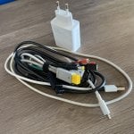
To make a PD4Wii or PD4WiiU yourself, you will need the following parts:

- 3D prints of the appropriate parts for your console.
(Shell can be printed from any material, use PETG, ABS, or something similar in strength for the Power Plug!)

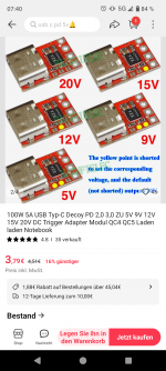
- A USB-C decoy that fits in the shell, configured to provide the appropriate voltage, either a PDC004 or a ZYPDH.
(The PDC004 is cheaper than the ZYPDH but is limited to a maximum current of 3.0A and only supports USB-PD, meaning it won't work with QC-only chargers!)

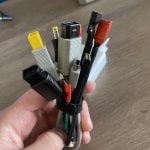
- D-Sub contacts such as the HARTING 09670007268 that fit the holes of the Power Plug.
(If you are aware of any alternatives, please post a comment about them.)

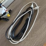
- Wire that's capable of safely carrying 5A or more.

(Preferably wires with differently colored shrouds, for example, red and black.)

- A Multimeter to double-check your wiring and to diagnose stuff.

Step 1: Printing the parts
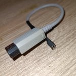
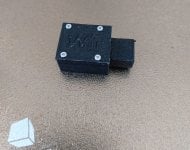
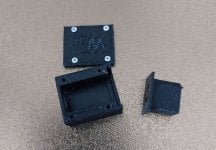
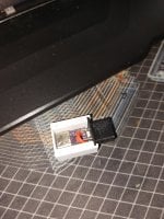
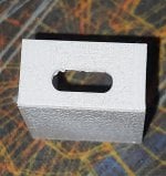
Download and extract the attached archive to some location where you'll find it again, i.e. your Desktop. If you don't have a 3D printer, it's time to find a reputable 3D printing provider and pay them to print the STLs. If you have a 3D Printer you should import the STLs into your Slicer and print them. I used a 0.2mm Nozzle for my prints, a 0.4mm one should work too, however. Remember to print the Power Plug from a strong material such as PETG or ABS, avoid using PLA for it. Print the Power Plug at a relatively low speed, it'll help a lot with stringing and other issues that may arise from fast print speeds. I printed it at 25mm/s which took about 10 minutes to complete. Once you've completed printing the parts clean them up if necessary and continue to the next step. Your prints should look somewhat like this:
shell2.jpg
Shell1.jpg
plug1.jpg
plug2.jpg

Step 2: Preparing the USB-C Decoy
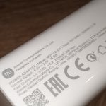
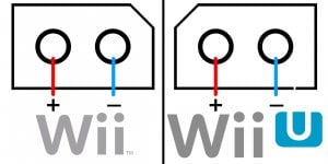
Verify that the Decoy is delivering the appropriate voltage using your multimeter (You'll want 12V for a Wii and 15V for a Wii U). If you're using the PDC004 and are getting the wrong voltage you'll have to replace it with another one. If you are using the ZYPDH, short the jumper corresponding to the wanted voltage and measure again. Cut two pieces of wire to about 1.5cm in length and strip about 2 - 3mm on both ends. Solder one end to the D-Sub contact and the other one to the output pad on the PD Decoy. Gently insert the D-Sub contacts into the holes on the Power Plug while minding the polarity. Refer to the pinout on the original brick or refer to this image:

pinout.jpg

Once fully inserted, you may want to fixate the contacts using hot glue or something similar to prevent them from slipping out of there later, possibly shorting something in that event.

Step 3: Putting it all together
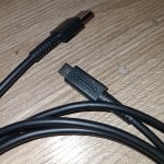
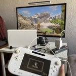
Place the Decoy into the shell, aligning the USB-C port with the opening. It does not have to be 100% aligned, but it should be good enough to be able to insert the cable later. Carefully push the Power Plug into its slot until it's fully seated. Put the lid on the shell and screw it in using fitting screws (such as the Triwing screws used in Joy-Cons). Congratulations! You now have your own PD4Wii / PD4WiiU!

aaa1.jpg
aaa2.jpg
aaa3.jpg
 

Attachments

  • shell2.jpg
    shell2.jpg
    117.1 KB · Views: 55
  • pinout.jpg
    pinout.jpg
    122.7 KB · Views: 52
  • STLs for 3D printing.7z
    89 KB · Views: 38
Last edited by EnterpriseFreak,

Liverbird

Member
Newcomer
Joined
May 28, 2023
Messages
6
Trophies
0
Age
32
XP
100
Country
Chile
Hi! I want to thank you for this tutorial, in addition, I have some questions about the following situation that I have:

Purchased the decoy you mentioned (and also an extra different decoy to try), configured them to output 12v to use with the Wii, but for some reason I cannot get them to actually output 12v, they only output 9v, wich of course is not enough to power the Wii...

Tried the following:

Decoys used: PDC004 and YZX-ZYPDH
- Bridged the 2 solder points to get 12v
- Tried 3 power supplies (Apple, Xiaomi, Nintendo Switch) and got the following multimeter readings: Apple 9v, Xiaomi 9v too, Nintendo Switch 5v... (???)

Which power supply do you recommend to use with this mod? Maybe the ones I'm using are not compatible or something? I don't know what I'm doing wrong to be honest...

Any advice would be appreciated, thanks!
 

EnterpriseFreak

Well-Known Member
OP
Newcomer
Joined
Sep 2, 2021
Messages
92
Trophies
0
Age
22
XP
979
Country
Germany
Hi! I want to thank you for this tutorial, in addition, I have some questions about the following situation that I have:

Purchased the decoy you mentioned (and also an extra different decoy to try), configured them to output 12v to use with the Wii, but for some reason I cannot get them to actually output 12v, they only output 9v, wich of course is not enough to power the Wii...

Tried the following:

Decoys used: PDC004 and YZX-ZYPDH
- Bridged the 2 solder points to get 12v
- Tried 3 power supplies (Apple, Xiaomi, Nintendo Switch) and got the following multimeter readings: Apple 9v, Xiaomi 9v too, Nintendo Switch 5v... (???)

Which power supply do you recommend to use with this mod? Maybe the ones I'm using are not compatible or something? I don't know what I'm doing wrong to be honest...

Any advice would be appreciated, thanks!

Hi there!
The most probable cause as to why you're getting the wrong voltage is that the chargers you're using do not support outputting 12v.

The thing about USB-PD negociation is that it's not a give me <x> volt or give me nothing kind of situation, rather it's a give <x> volt at most or less situation.

When you connect a PD-compliant charger to a device that supports receiving power via USB-C the devices will negotiate what voltage to supply. If the requested max. safe voltage cannot be supplied by the charger it'll instead provide a lower voltage. (5v in case of the Switch charger since it can only do 5v and 15v, 9v for the other chargers you used.)

You have to get a charger that's able to output current at a voltage of 12v, additionally it should at least be able to sustain a load of 3 amps or more.

I myself got a relatively cheap no name 65W charger from a local store that supports the whole range from 5v to 20v.

By the way, never try to use generic phone chargers for something like this. There's a lot that could go wrong there. Best case it'll simply refuse to work, worst cause you'll blow a fuse or damage something. The wires inside the cables bundled with most phone chargers might not even be able to safely handle 3 amps depending on how thick they are.
 

Liverbird

Member
Newcomer
Joined
May 28, 2023
Messages
6
Trophies
0
Age
32
XP
100
Country
Chile
Hi there!
The most probable cause as to why you're getting the wrong voltage is that the chargers you're using do not support outputting 12v.

The thing about USB-PD negociation is that it's not a give me <x> volt or give me nothing kind of situation, rather it's a give <x> volt at most or less situation.

When you connect a PD-compliant charger to a device that supports receiving power via USB-C the devices will negotiate what voltage to supply. If the requested max. safe voltage cannot be supplied by the charger it'll instead provide a lower voltage. (5v in case of the Switch charger since it can only do 5v and 15v, 9v for the other chargers you used.)

You have to get a charger that's able to output current at a voltage of 12v, additionally it should at least be able to sustain a load of 3 amps or more.

I myself got a relatively cheap no name 65W charger from a local store that supports the whole range from 5v to 20v.

By the way, never try to use generic phone chargers for something like this. There's a lot that could go wrong there. Best case it'll simply refuse to work, worst cause you'll blow a fuse or damage something. The wires inside the cables bundled with most phone chargers might not even be able to safely handle 3 amps depending on how thick they are.

Turns out you are right, checked my chargers and none of them can supply exactly 12V.
I've also read that 12V isn't an "standard" voltage for the USB-C PD protocol.

So, I would need to get an appropiate power supply and a proper USB-C cable that can handle the required current.

Thanks for your help!
 

Liverbird

Member
Newcomer
Joined
May 28, 2023
Messages
6
Trophies
0
Age
32
XP
100
Country
Chile
Since I don't have a 3D printer handy, I decided to make the mod a little differently...

Instead of printing the connector, I used the connector from a dead Wii PSU and soldered it to the decoy.

Turns out my Xiaomi charger was indeed compatible, I just needed a good quality USB-C cable, the one that comes with the Switch Pro Controller did the trick for me to actually get the 12v needed. Since this charger uses QC3, the PD004 decoy wouldn't give me 12v, so instead I had to use the YZX-ZYPDH decoy which is compatible with the QC3 protocol that this charger uses.

Now the Wii powers on with no issues!

I'm seriously considering to do the same mod to my other consoles, my PS2 Slim for example, I have many decoys to try!

Thanks again for your idea!
 

Attachments

  • IMG_20230530_181442.jpg
    IMG_20230530_181442.jpg
    3 MB · Views: 74
  • IMG_20230530_181539.jpg
    IMG_20230530_181539.jpg
    2.5 MB · Views: 66
  • IMG_20230530_181137.jpg
    IMG_20230530_181137.jpg
    462.4 KB · Views: 77
  • IMG_20230530_181125.jpg
    IMG_20230530_181125.jpg
    2.3 MB · Views: 70
  • IMG_20230530_181325.jpg
    IMG_20230530_181325.jpg
    2.4 MB · Views: 64
  • Wii USB-C - Imgur.mp4
    1.9 MB
  • Like
Reactions: EnterpriseFreak

jacobsson

Well-Known Member
Member
Joined
Oct 30, 2019
Messages
165
Trophies
0
Age
38
XP
769
Country
Sweden
This is a nice mod considering how bulky the 75w Wii U ac-adapter is!
I'd love to explore this subject some more, but one thing that bugs me is the 3 amp limit of PD protocol for any voltage under 20v.

That would mean that we're limited to 45W (15v @3A) using these decoys?
I'd love to see a small footprint mod of these modules that triggers 20v and buck converts it to 15v in order to still tap into that 5a max.
 

EnterpriseFreak

Well-Known Member
OP
Newcomer
Joined
Sep 2, 2021
Messages
92
Trophies
0
Age
22
XP
979
Country
Germany
This is a nice mod considering how bulky the 75w Wii U ac-adapter is!
I'd love to explore this subject some more, but one thing that bugs me is the 3 amp limit of PD protocol for any voltage under 20v.

That would mean that we're limited to 45W (15v @3A) using these decoys?
I'd love to see a small footprint mod of these modules that triggers 20v and buck converts it to 15v in order to still tap into that 5a max.

From all my testing the Wii U never went above ~30w power consumption even when playing demanding games like Breath of the Wild so even being limited to 3A should leave more than enough head room (Things might look different when someone overclocks the GPU using de_fuse, though.)

That being said, this is an option I might consider trying myself soon(TM). I wanted to rewrite this guide anyway, add more pictures and so on. Might as well add a second option for creating a dongle that can tap into the 5A limit, even if that one might end up a little bit bulkier than the current solution.

Since I got myself a 3D printer recently, I can finally test the designs without having to ask someone if he can do a test print for me every time I change something. That makes the whole process a whole lot easier for me. Just have to get the hang of a real CAD program first. TinkerCAD is cool and all but let's be honest here, it was never intended to make things like this so it's a small miracle this worked out in the first place.
 
  • Like
Reactions: jacobsson

jacobsson

Well-Known Member
Member
Joined
Oct 30, 2019
Messages
165
Trophies
0
Age
38
XP
769
Country
Sweden
From all my testing the Wii U never went above ~30w power consumption even when playing demanding games like Breath of the Wild so even being limited to 3A should leave more than enough head room (Things might look different when someone overclocks the GPU using de_fuse, though.)

That being said, this is an option I might consider trying myself soon(TM). I wanted to rewrite this guide anyway, add more pictures and so on. Might as well add a second option for creating a dongle that can tap into the 5A limit, even if that one might end up a little bit bulkier than the current solution.

Since I got myself a 3D printer recently, I can finally test the designs without having to ask someone if he can do a test print for me every time I change something. That makes the whole process a whole lot easier for me. Just have to get the hang of a real CAD program first. TinkerCAD is cool and all but let's be honest here, it was never intended to make things like this so it's a small miracle this worked out in the first place.
I'd love to see such guide!
If you don't mind, what would be the general aproach for achieving this? I don't mind tinkering and micro soldering.
I'm the kind of person who bypass the 500mA limit of the USB in order to charge gamepads, multiple WiiMotes and running a harddrive.
 

EnterpriseFreak

Well-Known Member
OP
Newcomer
Joined
Sep 2, 2021
Messages
92
Trophies
0
Age
22
XP
979
Country
Germany
I'd love to see such guide!
If you don't mind, what would be the general aproach for achieving this? I don't mind tinkering and micro soldering.
I'm the kind of person who bypass the 500mA limit of the USB in order to charge gamepads, multiple WiiMotes and running a harddrive.
I'd probably go with the approach you mentioned before. Using a decoy to trigger 20v at 5A and then stepping it down to 15v for use with the Wii U. I was just looking up other versions of USB-PD to see if there's versions of the protocol to allow native 15v @ 5A but for some reason above 3A is only available for 20v.
 

Liverbird

Member
Newcomer
Joined
May 28, 2023
Messages
6
Trophies
0
Age
32
XP
100
Country
Chile
This is a nice mod considering how bulky the 75w Wii U ac-adapter is!
I'd love to explore this subject some more, but one thing that bugs me is the 3 amp limit of PD protocol for any voltage under 20v.

That would mean that we're limited to 45W (15v @3A) using these decoys?
I'd love to see a small footprint mod of these modules that triggers 20v and buck converts it to 15v in order to still tap into that 5a max.
In my case I went for a decoy that's PD and QC compatible, the ZYPDH. It has the following specs: 100W 5A USB Type-C Decoy PD 2.0 3.0 TO 5V 9V 12V 15V 20V DC Trigger Adapter Module QC4 QC5 Charge Charging Notebook

Can't post links, look it up on Ali ;)

Soldered the Wii U connector to the decoy, used the charger and USB-C cable from my Xiaomi 11T that's QC3 and voilá... The charger can provide up to 67W and the cable is rated for 6A, although the same cable for some reason can't provide 12v, it provides 9 and 15. For that reason, for the consoles that need 12v (like the GC and Wii), I used a Switch Pro Controller USB cable than CAN provide 12v with the same charger.

The PD protocol seems to be more limited than QC.

Ended up making a bunch of those adapters for my consoles, I been using them for 1-2 monts without any issues.
 

Attachments

  • 357380816_10228404142501246_725610838979083040_n.jpg
    357380816_10228404142501246_725610838979083040_n.jpg
    726.9 KB · Views: 57
  • 357084435_10228404140781203_7230221169092609387_n.jpg
    357084435_10228404140781203_7230221169092609387_n.jpg
    531.3 KB · Views: 64
  • 355852897_10228404141301216_495655560406829144_n.jpg
    355852897_10228404141301216_495655560406829144_n.jpg
    512 KB · Views: 53
  • 357393171_10228404138021134_8006041429039479676_n.jpg
    357393171_10228404138021134_8006041429039479676_n.jpg
    605.7 KB · Views: 59
  • 357443393_10228404140141187_7957228811607909618_n.jpg
    357443393_10228404140141187_7957228811607909618_n.jpg
    539.2 KB · Views: 63
  • 357133313_10228404141261215_252291485704241744_n.jpg
    357133313_10228404141261215_252291485704241744_n.jpg
    827.5 KB · Views: 58
Last edited by Liverbird,

EnterpriseFreak

Well-Known Member
OP
Newcomer
Joined
Sep 2, 2021
Messages
92
Trophies
0
Age
22
XP
979
Country
Germany
In my case I went for a decoy that's PD and QC compatible, the ZYPDH. It has the following specs: 100W 5A USB Type-C Decoy PD 2.0 3.0 TO 5V 9V 12V 15V 20V DC Trigger Adapter Module QC4 QC5 Charge Charging Notebook

Can't post links, look it up on Ali ;)

Soldered the Wii U connector to the decoy, used the charger and USB-C cable from my Xiaomi 11T that's QC3 and voilá... The charger can provide up to 67W and the cable is rated for 6A, although the same cable for some reason can't provide 12v, it provides 9 and 15. For that reason, for the consoles that need 12v (like the GC and Wii), I used a Switch Pro Controller USB cable than CAN provide 12v with the same charger.

The PD protocol seems to be more limited than QC.

Ended up making a bunch of those adapters for my consoles, I been using them for 1-2 monts without any issues.
Thanks for you input. I've just looked it up on Ali. Can you confirm this is the one you've been using?
 

Attachments

  • Screenshot_20230815-074002_AliExpress.png
    Screenshot_20230815-074002_AliExpress.png
    1.2 MB · Views: 71
  • Like
Reactions: Liverbird

EnterpriseFreak

Well-Known Member
OP
Newcomer
Joined
Sep 2, 2021
Messages
92
Trophies
0
Age
22
XP
979
Country
Germany
Well, I just ordered one of those ZYPDH QC5 Decoys from AliExpress. Looking at the specs of QC4.0 and QC5.0 listed on Wikipedia, 15v 5A seems to be possible using it so let's see how it goes. Just gotta wait for the thing to travel across the world now. They do claim to have it at my doorstep within the next twelve days so let's see how that goes.

The seller thankfully listed the (hopefully accurate) dimensions of the PCB in the listing so I went ahead and re-designed the shell of the dongle in advance. Compared to the original PD4Wii and PD4WiiU it gained some width (about 5mm) but also has gotten a bit shorter, making it a bit weird to look at (but whatever, it's functionality we're after, not looks).

I've have attached some pictures of the draft print to give everyone interested an idea how the new version will look. That's also going to be the version that the new version of the guide will be written for.

Please feel free to let me know your thoughts.
 

Attachments

  • 1.jpg
    1.jpg
    534 KB · Views: 68
  • 2.jpg
    2.jpg
    437.7 KB · Views: 61
  • 3.jpg
    3.jpg
    758.6 KB · Views: 62

EnterpriseFreak

Well-Known Member
OP
Newcomer
Joined
Sep 2, 2021
Messages
92
Trophies
0
Age
22
XP
979
Country
Germany
@EnterpriseFreak nice job!
I wonder if a clip-together design would be able to shrink the footprint even more?
Another plus is that you wouldn't need screws.

I don't think removing the screws in favor of a design that uses clips would really save that much space (maybe 1mm at most) to be honest with you.

That design has about the size of a Switch game cart and they're already pretty small. Most of the added width comes from the changes I made to how the plug part of the dongle is inserted into the shell now. In the original design it more or less was a yolo approach, get the USB-C port to align with the hole somehow and push the plug in as hard as you can until its notches comes out from the two small holes in the shell.

The new design uses a much more sane approach by having a dedicated mounting spot for the plug part. You slide it in, make sure its all the way in there and then push the crimp contacts into the openings (and maybe add some hot glue then to make sure they won't slide out of there later on).

If you make any mistakes with aligning the USB-C port or whatever, maybe you accidentally used a Wii U plug for a Wii dongle you can just undo that mistake by removing the connector again and replacing it with the appropriate one. With the old notches design you pretty much had to destroy the entire print at that point to get to the guts to fix any mistake you may have made.

---

EDIT:
Two more things I didn't think about mentioning before:

- The screws theoretically speaking can be replaced using a thin but strong adheasive. Not the best solution but a solution regardless of that (And with a thin enough adheasive it might not even be visible).

- PLA becomes rather stiff once it has cooled off after printing which could become an issue with a clip system instead of screws. Sure, you could *probably* blow some hot air using a hair dryer or similar on the material to soften it up temporarily but I still find screws to be a better solutions than clips.
 

Attachments

  • IMG_20230818_065804.jpg
    IMG_20230818_065804.jpg
    1.3 MB · Views: 58
Last edited by EnterpriseFreak,

EnterpriseFreak

Well-Known Member
OP
Newcomer
Joined
Sep 2, 2021
Messages
92
Trophies
0
Age
22
XP
979
Country
Germany
Well, I just ordered one of those ZYPDH QC5 Decoys from AliExpress. Looking at the specs of QC4.0 and QC5.0 listed on Wikipedia, 15v 5A seems to be possible using it so let's see how it goes. Just gotta wait for the thing to travel across the world now. They do claim to have it at my doorstep within the next twelve days so let's see how that goes.

Things might just actually go faster than expected, I just received an status update on the shipment that it cleared customs today so maybe I'll have a working protoype at the end of this week. I've made some very minor adjustments to the shell making it possible to also use the PDC004 from the original design if wanted, this way there's a "budget" option (a PDC004 costs like 50 cents) which allows for 3A max and a "premium" (ZYPDH costs like 3.50€) option that allows for the full 5A. More choice is always nice.

By the way, anyone know a relatively cheap but decent load tester? Like I mentioned in one of my previous posts, a stock Wii U will struggle to use more than 30W and since the whole idea behind using a QC capable decoy is to provide up to 65W for OC'd consoles and consoles with the 500mA limit per USB port removed I'd like to make sure we're actually getting (close to) the 5 amps QC should allow for.
 

EnterpriseFreak

Well-Known Member
OP
Newcomer
Joined
Sep 2, 2021
Messages
92
Trophies
0
Age
22
XP
979
Country
Germany
Well, it's been a while. I've gotten the boards a couple of days ago but I've been too busy until now to actually put the thing together. I just finished putting the first ZYPDH based dongle together and it's working as expected. Might just be me but I have the feeling that the handshake between the ZYPDH and the charger is much slower than the one done by the PDC004 since it's taking one or two seconds for the console to actually receive power. As I said, I might just be imagining it or maybe it's actually taking longer because it supports QC and USB-PD and takes longer to try all profiles.

Anyway, I'll try to start reworking the OP soon, can't promise when that's done, howecer.
 

Attachments

  • 2023-08-27-12-15-01-785.jpg
    2023-08-27-12-15-01-785.jpg
    763 KB · Views: 44

Liverbird

Member
Newcomer
Joined
May 28, 2023
Messages
6
Trophies
0
Age
32
XP
100
Country
Chile
Well, it's been a while. I've gotten the boards a couple of days ago but I've been too busy until now to actually put the thing together. I just finished putting the first ZYPDH based dongle together and it's working as expected. Might just be me but I have the feeling that the handshake between the ZYPDH and the charger is much slower than the one done by the PDC004 since it's taking one or two seconds for the console to actually receive power. As I said, I might just be imagining it or maybe it's actually taking longer because it supports QC and USB-PD and takes longer to try all profiles.

Anyway, I'll try to start reworking the OP soon, can't promise when that's done, howecer.
Yep. that's normal. It happens under the following scenarios:

1. You just cold-plugged in the charger to the mains: It takes a couple of seconds to negotiate the appropiate voltage
2. Right after plugging in a console, you plugged in another one that requires a different voltage

It basically takes like 2 seconds to negotiate the required voltage, but for example, if you plug in a Wii, it's gonna take 2 seconds to give it power, but if you plug in a Gamecube right after, it's gonna be instant, because there will not be any voltage negotiation since both consoles use 12v and the charger is already "set" to give 12v.

Good thing it only happens when you first plug in a console, but if you leave it connected there is no problem at all because the voltage is already set on the charger, so it's gonna power on instantly as it's supposed to do.
 

Site & Scene News

Popular threads in this forum

General chit-chat
Help Users
    Psionic Roshambo @ Psionic Roshambo: In emulation overclocked FX chips makes a pretty big difference in frame rate