

You are using an out of date browser. It may not display this or other websites correctly.
You should upgrade or use an alternative browser.
You should upgrade or use an alternative browser.
2023 Newest Hwfly Oled V5,V5+ deluxe
- Thread starter FXDX
- Start date
- Views 6,478
- Replies 21


- Joined
- Sep 2, 2020
- Messages
- 1,295
- Trophies
- 0
- Age
- 39
- Location
- TORONTO
- Website
- form.jotform.com
- XP
- 2,231
- Country


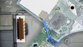
Accidentally in the pictureA v1 flex picture came in by accident


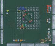
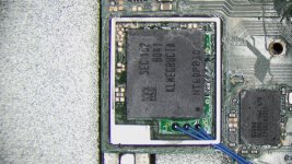
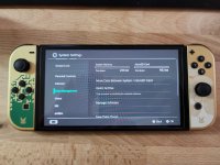
What is the Hwfly Oled V5 deluxe? Is that newer than instinct v6?I installed today the new 2023 Newest Hwfly Oled V5,V5+ deluxe. Everything went normally and works well. I am attaching some pictures of its installation on Switch Oled.
View attachment 378565View attachment 378567View attachment 378566View attachment 378573View attachment 378569
I don't see it listed in the official hwfly store.
What is the Hwfly Oled V5 deluxe? Is that newer than instinct v6?
I don't see it listed in the official hwfly store.
Do even know at this point who the manufacturer is, or what store is realy official?
To my eye there a dozen manufacturers of the the HWFLY all doing their own thing.
Do even know at this point who the manufacturer is, or what store is realy official?
To my eye there a dozen manufacturers of the the HWFLY all doing their own thing.
There is a store that all the big time GBAtemp members recommend that is somewhat hidden. I assume this is the official store.
I do intend on installing one of these with the clk, cmd and dat0 pcb on the emmc module that the deluxe kit comes with into a oled as that should be more long term reliable (and tidier), it looks like the solder pads should line up with the traces where that shield outcrop is, I do intend on using kapton tape to help me align it and using a wash bottle with ipa to flush the remaining tack flux out of the underside between the BGA pads to avoid issues down the line (or immediately/shortly after installation)


I do intend on installing one of these with the clk, cmd and dat0 pcb on the emmc module that the deluxe kit comes with into a oled as that should be more long term reliable (and tidier), it looks like the solder pads should line up with the traces where that shield outcrop is, I do intend on using kapton tape to help me align it and using a wash bottle with ipa to flush the remaining tack flux out of the underside between the BGA pads to avoid issues down the line (or immediately/shortly after installation)
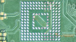
the latest batch of green adapters that I ordered had really bad quality on the solder balls (too small and uneven sizes), so I had to reball them on both sides before using, or one or several balls wouldn't make contact. Make sure to measure all important points against gnd after the green adapter has been attached, before attaching emmc. attaching a pic of all points that are connected so something on the oled motherboard. The remaining points/balls are unused and don't matter.
Post automatically merged:
What advantages does this have over the Picofly?
depends on what you mean with picofly. if you mean the DIY kit with an rp2040-zero, resistors and mosfet, then this one is easier to install. If you mean the premade pcb's from aliexpress with rp2040/picofly on it, then none whatsoever.
Attachments
Last edited by deeps,
the latest batch of green adapters that I ordered had really bad quality on the solder balls (too small and uneven sizes), so I had to reball them on both sides before using, or one or several balls wouldn't make contact. Make sure to measure all important points against gnd after the green adapter has been attached, before attaching emmc. attaching a pic of all points that are connected so something on the oled motherboard. The remaining points/balls are unused and don't matter.
I have very much questioned 3 I have on hand even to the naked eye, I'll attempt to reflow them first otherwise I'll reball them with the stencil I got made up by aisler in the case I needed to
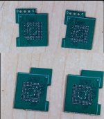
I have 10 of the reball / green adapters. They were either missing some solder balls or the solder balls were not even height. I did question the seller and they confirmed that they come with lead-free solder. Since I had to fix the missing balls / ball height anyway, I just reballed them with leaded solder to reduce soldering temps. I used preformed balls, i imagine this is easier with a direct heat stencil / solder paste. I'm waiting on a stencil with holder for emmc to see if I can use that instead of preformed balls, but since the adapter is shaped differently than an emmc chip, it might not work and use of a stencil without holder might be needed.I have very much questioned 3 I have on hand even to the naked eye, I'll attempt to reflow them first otherwise I'll reball them with the stencil I got made up by aisler in the case I needed to
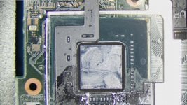
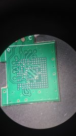
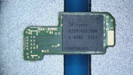
I've installed 4x of these reball adapters now, i'm a fan of how neat it is and also you don't need to cut soc frame if you are brave and just grab clk from the adapter (I've done this braver install on my personal TOTK oled which came with a sk hynix chip). However you run the risk of the emmc failing during the desoldering and soldering process (sk hynix reputation for failing / being brittle). It's safer to do traditional install with dat0 adapter to grab a backup first before tidying it up with reball adapter.
You can also install these in 2 different orders. Option 1 would be solder the adapter to board then solder the emmc to the adapter (recommneded). The other option would be install the emmc on to adapter then solder the whole thing onto the main board. Option 1 puts less heat onto the emmc chip (since option 2, see below, requires putting heat through the emmc onto the reball adapter), however you can't really do the nudge test on the emmc chip since the balls under the adapter are probably also molten (probably more true if you reballed with leaded solder balls) and the whole assembly moves when you nudge it (surface tension). If you do option 2 you can do the nudge test on the emmc when soldering it onto the reball adapter then you can nudge the reball adapter (whole thing would move) to confirm its on the mainboard correctly.
Also consider upgrading nand if you're going to pull emmc anyway, I upgraded mine and mounted the old emmc onto an emmc reader to make backup (I didn't cut soc frame on my personal switch).
Attachments
-
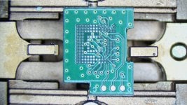 Reball Adapter Original Top.jpg426.7 KB · Views: 62
 -
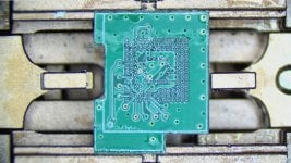 Reball Adapter Original Bottom.jpg433.4 KB · Views: 66
 -
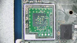 Reball Adapter Installed.jpg497.4 KB · Views: 61
 -
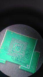
 Samsung 256GB EMMC Installed.jpg561.3 KB · Views: 57
 -
 EMMC 3x32 AWG Wire.jpg402.9 KB · Views: 61
 -
 SoC Flex.jpg431.2 KB · Views: 49
 -
 OLED System Menu.jpg3.3 MB · Views: 54
Last edited by Johnny_debt,
I have 10 of the reball / green adapters. They were either missing some solder balls or the solder balls were not even height. I did question the seller and they confirmed that they come with lead-free solder. Since I had to fix the missing balls / ball height anyway, I just reballed them with leaded solder to reduce soldering temps. I used preformed balls, i imagine this is easier with a direct heat stencil / solder paste. I'm waiting on a stencil with holder for emmc to see if I can use that instead of preformed balls, but since the adapter is shaped differently than an emmc chip, it might not work and use of a stencil without holder might be needed.
I've installed 4x of these reball adapters now, i'm a fan of how neat it is and also you don't need to cut soc frame if you are brave and just grab clk from the adapter (I've done this braver install on my personal TOTK oled which came with a sk hynix chip). However you run the risk of the emmc failing during the desoldering and soldering process (sk hynix reputation for failing / being brittle). It's safer to do traditional install with dat0 adapter to grab a backup first before tidying it up with reball adapter.
You can also install these in 2 different orders. Option 1 would be solder the adapter to board then solder the emmc to the adapter (recommneded). The other option would be install the emmc on to adapter then solder the whole thing onto the main board. Option 1 puts less heat onto the emmc chip (since option 2, see below, requires putting heat through the emmc onto the reball adapter), however you can't really do the nudge test on the emmc chip since the balls under the adapter are probably also molten (probably more true if you reballed with leaded solder balls) and the whole assembly moves when you nudge it (surface tension). If you do option 2 you can do the nudge test on the emmc when soldering it onto the reball adapter then you can nudge the reball adapter (whole thing would move) to confirm its on the mainboard correctly.
Also consider upgrading nand if you're going to pull emmc anyway, I upgraded mine and mounted the old emmc onto an emmc reader to make backup (I didn't cut soc frame on my personal switch).
What is the benefit of using the reball adapter instead of just using the normal dat0 adapter that you solder the 4 points to?
1. When compared to traditional DAT0 adapter, the reball adapter provides for solid soldered connection, so you won't ever have any issue with DAT0 connection coming loose (I've had mixed experience with DAT0 adapter with some folks having no issues with corner adapter and some folks having issues with the 4 corner version and vice versa).What is the benefit of using the reball adapter instead of just using the normal dat0 adapter that you solder the 4 points to?
2. When compared to traditional DAT0 adapter that has been reflowed, you won't have any issues with cracked solder joints over time.
3. You also get solid connection with cmd and clk points, avoiding risk of destroying the cmd resistor and clk point (when exposing it although I've only personally seen one case where clk connection was severed but it was repairable).
In summary, the reball adapter generally provides for much better soldered connection points for DAT0, CMD and CLK but requires higher soldering skills because it requires BGA soldering technique and increased risk because eMMC is being removed (although risk can be mitigated with a backup of the nand using a traditional install, dat0 adapter, expose clk and cmd resistor connection first).

So this method would require the removal of your emmc and then reballing this with emmc. And then reballing it onto the motherboard? Am I following correctly? And this is better than traditional emmc reball becuse there are dedicated solder points to dat0, cmd and clk. Sounds good. But unsure on the fixing it together with emmc. Any link to merchant who sell these? thanks.I have 10 of the reball / green adapters. They were either missing some solder balls or the solder balls were not even height. I did question the seller and they confirmed that they come with lead-free solder. Since I had to fix the missing balls / ball height anyway, I just reballed them with leaded solder to reduce soldering temps. I used preformed balls, i imagine this is easier with a direct heat stencil / solder paste. I'm waiting on a stencil with holder for emmc to see if I can use that instead of preformed balls, but since the adapter is shaped differently than an emmc chip, it might not work and use of a stencil without holder might be needed.
I've installed 4x of these reball adapters now, i'm a fan of how neat it is and also you don't need to cut soc frame if you are brave and just grab clk from the adapter (I've done this braver install on my personal TOTK oled which came with a sk hynix chip). However you run the risk of the emmc failing during the desoldering and soldering process (sk hynix reputation for failing / being brittle). It's safer to do traditional install with dat0 adapter to grab a backup first before tidying it up with reball adapter.
You can also install these in 2 different orders. Option 1 would be solder the adapter to board then solder the emmc to the adapter (recommneded). The other option would be install the emmc on to adapter then solder the whole thing onto the main board. Option 1 puts less heat onto the emmc chip (since option 2, see below, requires putting heat through the emmc onto the reball adapter), however you can't really do the nudge test on the emmc chip since the balls under the adapter are probably also molten (probably more true if you reballed with leaded solder balls) and the whole assembly moves when you nudge it (surface tension). If you do option 2 you can do the nudge test on the emmc when soldering it onto the reball adapter then you can nudge the reball adapter (whole thing would move) to confirm its on the mainboard correctly.
Also consider upgrading nand if you're going to pull emmc anyway, I upgraded mine and mounted the old emmc onto an emmc reader to make backup (I didn't cut soc frame on my personal switch).
This is the intended method to install the reball adapter:So this method would require the removal of your emmc and then reballing this with emmc. And then reballing it onto the motherboard? Am I following correctly? And this is better than traditional emmc reball becuse there are dedicated solder points to dat0, cmd and clk. Sounds good. But unsure on the fixing it together with emmc. Any link to merchant who sell these? thanks.
1) Remove eMMC
2) Remove excess solder on eMMC so you just have pads
3) Remove excess solder on mainboard where eMMC sat
4) Install reball adapter onto mainboard (comes with solder balls on both sides of the PCB)
5) Reinstall eMMC on top of the reball adapter
Two optional steps that you may perform as numbered to check your work, I've also attached diode readings on the pads to help others who want to use this adapter.
3a) Take diode readings on the mainboard where eMMC chip sat for purposes of confirming solder job
4a) Confirm diode readings on the reball adapter corresponding pads top side against the readings taken on 3a to confirm alignment of reball adapter.
The reason you don't reball the eMMC is that the reball adapter does not have all the pads that correspond to the 153 pads on the eMMC chip. This is because they used some of the space on the reball adapter pcb for traces to pull the cmd, clk and DAT0 to the side of the board so it is accessible for modchip install. This is fine because out of the 153 pads on the eMMC chip, only about 20-30 are used, the remaining are 'no connect' and are only there to hold the chip in place. The missing solder ball pads used to pull the traces for cmd, clk and DAT0 are no connects. Hence if the reball adapter you receive is of bad quality then you would need to reball the reball adapter and not the eMMC chip. If you reball the eMMC chip you would end up with excess solder balls over the reball adapter and may complicate the installation process as excess solder ball may lead to merging of solder balls. You may optionally wan to reball the reball adapter anyway to use leaded solder instead of the lead-free that comes stock on the reball adapter.
Attachments
This one here would be essentially mean you place the emmc ontop of the now 'stuck-on/flowed' on the motherboard adaptor via a reflow method because the green adaptor is already primed with double sides of solder balls. So you reflow two times after the initial clean of the emmc and main board. looks good.5) Reinstall eMMC on top of the reball adapter
Correct,This one here would be essentially mean you place the emmc ontop of the now 'stuck-on/flowed' on the motherboard adaptor via a reflow method because the green adaptor is already primed with double sides of solder balls. So you reflow two times after the initial clean of the emmc and main board. looks good.
The eMMC adapter is not hard to install, you just can't rely on both markers on the mainboard since one is covered by the cmd, clk, dat points, so you rely on only one of the corner markers to align. The reball adapter doesn't take much heat since its not a full blown chip to get the solder balls on bottom to go molten. You can then follow the reball adapter white lines that help you align the eMMC chip. Be careful if you intend to nudge test your work since nudging the eMMC may move also the reball adapter.
Last edited by Johnny_debt,
I think it's the right one I re flowed at 350c for about a minute with a fair amount of chipquik's no-clean tack flux (SMD291) I did neglect to take a photo of it before hand alone, the balls do look better looking at them both to the naked eye and microscope. I'd be willing to use that in a mod after redoing the pads on it as I look at it under a microscope they are in reasonable balls and seem to not be oddly shaped as they were.
emmc wise, I'd be temped to ask some of the phone repair shops around me to see if they have one of those emmc bga153 socket dumpers to get a copy of the flash once it's off the switch before attempting to reinstall it to the switch
emmc wise, I'd be temped to ask some of the phone repair shops around me to see if they have one of those emmc bga153 socket dumpers to get a copy of the flash once it's off the switch before attempting to reinstall it to the switch
Attachments
Last edited by danwellby,
Oh i know all about nudging mistakes. It requires an ever so delicate of delicate touches. Almost feather like. If you can't do that, don't nudge it.Correct,
The eMMC adapter is not hard to install, you just can't rely on both markers on the mainboard since one is covered by the cmd, clk, dat points, so you rely on only one of the corner markers to align. The reball adapter doesn't take much heat since its not a full blown chip to get the solder balls on bottom to go molten. You can then follow the reball adapter white lines that help you align the eMMC chip. Be careful if you intend to nudge test your work since nudging the eMMC may move also the reball adapter.
I think it's the right one I re flowed at 350c for about a minute with a fair amount of chipquik's no-clean tack flux (SMD291) I did neglect to take a photo of it before hand alone, the balls do look better looking at them both to the naked eye and microscope. I'd be willing to use that in a mod after redoing the pads on it as I look at it under a microscope they are in reasonable balls and seem to not be oddly shaped as they were.
emmc wise, I'd be temped to ask some of the phone repair shops around me to see if they have one of those emmc bga153 socket dumpers to get a copy of the flash once it's off the switch before attempting to reinstall it to the switch
I think you would need to reball the eMMC for those clam sockets to get reading on the eMMC, so once again applying heat to the eMMC.
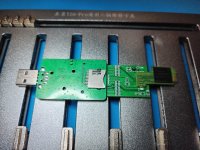
What I did with mine is that I went ahead and upgraded the nand to 256GB on my OLED switch but I didn't want to cut the SoC frame nor did I want to redo the whole process of soldering the original eMMC back onto the OLED switch to get a backup (I needed the backup to restore on the new upgraded nand). So instead, I resoldered the original eMMC onto a v1 switch board and used an eMMC reader I got off aliexpress to make a nand backup in ubuntu. So that's my long winded way of saying you can get a copy of the nand backup on the eMMC if you resoldered it back onto a v1 board and use a v1 switch with hekate to grab the backup.
It's like the perfect time to upgrade the nand once you have it off.
Attachments

Similar threads
- Replies
- 2
- Views
- 534
- Replies
- 32
- Views
- 3K
- Replies
- 9
- Views
- 1K
- Replies
- 4
- Views
- 3K
Site & Scene News
New Hot Discussed
-
-
28K views
Nintendo Switch firmware update 18.0.1 has been released
A new Nintendo Switch firmware update is here. System software version 18.0.1 has been released. This update offers the typical stability features as all other... -
21K views
Nintendo officially confirms Switch successor console, announces Nintendo Direct for next month
While rumors had been floating about rampantly as to the future plans of Nintendo, the President of the company, Shuntaro Furukawa, made a brief statement confirming... -
21K views
New static recompiler tool N64Recomp aims to seamlessly modernize N64 games
As each year passes, retro games become harder and harder to play, as the physical media begins to fall apart and becomes more difficult and expensive to obtain. The... -
21K views
TheFloW releases new PPPwn kernel exploit for PS4, works on firmware 11.00
TheFlow has done it again--a new kernel exploit has been released for PlayStation 4 consoles. This latest exploit is called PPPwn, and works on PlayStation 4 systems... -
20K views
Delta emulator now available on the App Store for iOS
The time has finally come, and after many, many years (if not decades) of Apple users having to side load emulator apps into their iOS devices through unofficial...by ShadowOne333 96 -
19K views
Nintendo takes down Gmod content from Steam's Workshop
Nintendo might just as well be a law firm more than a videogame company at this point in time, since they have yet again issued their now almost trademarked usual...by ShadowOne333 127 -
15K views
Name the Switch successor: what should Nintendo call its new console?
Nintendo has officially announced that a successor to the beloved Switch console is on the horizon. As we eagerly anticipate what innovations this new device will... -
15K views
A prototype of the original "The Legend of Zelda" for NES has been found and preserved
Another video game prototype has been found and preserved, and this time, it's none other than the game that spawned an entire franchise beloved by many, the very...by ShadowOne333 32 -
14K views
Anbernic reveals specs details of pocket-sized RG28XX retro handheld
Anbernic is back with yet another retro handheld device. The upcoming RG28XX is another console sporting the quad-core H700 chip of the company's recent RG35XX 2024... -
12K views
DOOM has been ported to the retro game console in Persona 5 Royal
DOOM is well-known for being ported to basically every device with some kind of input, and that list now includes the old retro game console in Persona 5 Royal...
-
-
-
263 replies
Name the Switch successor: what should Nintendo call its new console?
Nintendo has officially announced that a successor to the beloved Switch console is on the horizon. As we eagerly anticipate what innovations this new device will...by Costello -
227 replies
Nintendo officially confirms Switch successor console, announces Nintendo Direct for next month
While rumors had been floating about rampantly as to the future plans of Nintendo, the President of the company, Shuntaro Furukawa, made a brief statement confirming...by Chary -
127 replies
Nintendo takes down Gmod content from Steam's Workshop
Nintendo might just as well be a law firm more than a videogame company at this point in time, since they have yet again issued their now almost trademarked usual...by ShadowOne333 -
117 replies
New static recompiler tool N64Recomp aims to seamlessly modernize N64 games
As each year passes, retro games become harder and harder to play, as the physical media begins to fall apart and becomes more difficult and expensive to obtain. The...by Chary -
96 replies
Delta emulator now available on the App Store for iOS
The time has finally come, and after many, many years (if not decades) of Apple users having to side load emulator apps into their iOS devices through unofficial...by ShadowOne333 -
82 replies
Nintendo Switch firmware update 18.0.1 has been released
A new Nintendo Switch firmware update is here. System software version 18.0.1 has been released. This update offers the typical stability features as all other...by Chary -
80 replies
TheFloW releases new PPPwn kernel exploit for PS4, works on firmware 11.00
TheFlow has done it again--a new kernel exploit has been released for PlayStation 4 consoles. This latest exploit is called PPPwn, and works on PlayStation 4 systems...by Chary -
78 replies
"Nintendo World Championships: NES Edition", a new NES Remix-like game, launching July 18th
After rumour got out about an upcoming NES Edition release for the famed Nintendo World Championships, Nintendo has officially unveiled the new game, titled "Nintendo...by ShadowOne333 -
71 replies
DOOM has been ported to the retro game console in Persona 5 Royal
DOOM is well-known for being ported to basically every device with some kind of input, and that list now includes the old retro game console in Persona 5 Royal...by relauby -
71 replies
Ubisoft reveals 'Assassin's Creed Shadows' which is set to launch later this year
Ubisoft has today officially revealed the next installment in the Assassin's Creed franchise: Assassin's Creed Shadows. This entry is set in late Sengoku-era Japan...by Prans
-
Popular threads in this forum
General chit-chat
-
 Psionic Roshambo
Loading…
Psionic Roshambo
Loading…
-
-
 @
BigOnYa:
I'm good, how r u, sorry playing Starfield, n have tablet by me on chat, but was exploring a planet
@
BigOnYa:
I'm good, how r u, sorry playing Starfield, n have tablet by me on chat, but was exploring a planet -
-
-
-
-
-
-
-
-
S @ salazarcosplay:@Xdqwerty FMA seemed more metaphysical. Like Alchemy was a mysterious comic phenomenon, that gave you an experience.+1
In brotherhood it seemed more direct. Like there was a "god of alchemy that" one met. And it liked humbling people -
S @ salazarcosplay:At the end of the game Ed beather Truth at his own game giving up his ability to do alchemy
-
-
-
-
-
-
-
-
S @ salazarcosplay:@Xdqwerty good. thats great fma takes more time to to build up the beginning. brotherhood rushed the beginnign because the beginning had already been told+1
-
-
-
-
-