Hardware Switch not turning on

OwenG123

Member
OP
Newcomer
Joined
Mar 21, 2021
Messages
15
Trophies
0
Age
39
XP
67
Country
United Kingdom
Hi,
I have a switch that has no signs of life.

The usb-c port was physically damaged so I have replaced it, managed to get the old port off without damaging any pads and I believe the new port is soldered correctly (my first time doing one but I have tried reflowing it a couple of times just incase).

The switch when plugged in only draws 0.02A (the same as it was with the damaged port) and it does not matter which way around the usb-c plug is inserted.

I can't find any shorts around the board, fuse is OK, is it worth reflowing the usb-c port again? If not does anybody have any suggestions for where I should look next?
 

thesjaakspoiler

Well-Known Member
Member
Joined
Nov 20, 2018
Messages
988
Trophies
0
Age
124
XP
1,502
Country
Afghanistan
Check the battery voltage.
If that is sufficient (+3.7v) it should turn on if nothing else is damaged.
If it doesn't have enough voltage, try another battery.
If that also doesn't work, check the charger and USB chips.
You never know if the previous owner shorted out those 2 chips when he damaged the USB-C port.
 

OwenG123

Member
OP
Newcomer
Joined
Mar 21, 2021
Messages
15
Trophies
0
Age
39
XP
67
Country
United Kingdom
Thanks for the reply.
I will try a known good battery later and see if it will power on, the battery that is in there is measuring 2.4V.
 

OwenG123

Member
OP
Newcomer
Joined
Mar 21, 2021
Messages
15
Trophies
0
Age
39
XP
67
Country
United Kingdom
OK, I have tried a charged battery in it and it boots to a 2101-001 error.

It still only ever draws 0.018 - 0.020A at 5v.

I have re-checked and I still can't find any shorts around the board. My research leads me to believe that maybe I should replace the M92T36 chip next, unless anybody has any suggestions that I can use to narrow the fault down further?

Thankyou,
Owen
 

Pintglass

Well-Known Member
Member
Joined
Jan 28, 2019
Messages
364
Trophies
0
Age
52
XP
782
Country
United Kingdom
Thanks for the reply.
I will try a known good battery later and see if it will power on, the battery that is in there is measuring 2.4V.

Check to see what voltage you have on pin 9 of M92T36 when you have the charger plugged in, make sure you dont slip with the probes or you could short some thing out.
 

Pintglass

Well-Known Member
Member
Joined
Jan 28, 2019
Messages
364
Trophies
0
Age
52
XP
782
Country
United Kingdom
No, That was with power bank, I just tried with Nintendo charger and reading 0v on pin 9 and on the fuse above usb port. Nintendo charger is working (I just double checked on my working switch)

Do you get the same reading with the usb c connector reversed?
 

OwenG123

Member
OP
Newcomer
Joined
Mar 21, 2021
Messages
15
Trophies
0
Age
39
XP
67
Country
United Kingdom
Just to the left of the usb port on the underside of the board is a 6 pin Esd protection device check that you dont have continuity between pins 1-5 and pins 2-4

Hi,
Thanks for your help, I have no continuity between 1-5 and 2-4.

All the back pins on the usb-c port are secure (the ones you can see), I assume that even if the pins underneath the connector were not soldered properly that it would still charge with the plug in one way around but not the other?
 

Pintglass

Well-Known Member
Member
Joined
Jan 28, 2019
Messages
364
Trophies
0
Age
52
XP
782
Country
United Kingdom
Hi,
Thanks for your help, I have no continuity between 1-5 and 2-4.

All the back pins on the usb-c port are secure (the ones you can see), I assume that even if the pins underneath the connector were not soldered properly that it would still charge with the plug in one way around but not the other?

Check if you have continuity from the cc pins on the usb port to the test points just above the IC you just tested, you will need very fine probes or a small pin to get to the pins which you can't see but it is possible.

Check that you dont have continuity between pins 2-5 on the same IC as before
 

OwenG123

Member
OP
Newcomer
Joined
Mar 21, 2021
Messages
15
Trophies
0
Age
39
XP
67
Country
United Kingdom
Check if you have continuity from the cc pins on the usb port to the test points just above the IC you just tested, you will need very fine probes or a small pin to get to the pins which you can't see but it is possible.

Check that you dont have continuity between pins 2-5 on the same IC as before


OK, I dug out my extra fine probes and figured I would start on the ic, pins 2 - 5 are shorted. I also retested 1-5 and 2 - 4 and they are also shorted. I can only assume that I wasn't getting good contact with my other probes.
 

Pintglass

Well-Known Member
Member
Joined
Jan 28, 2019
Messages
364
Trophies
0
Age
52
XP
782
Country
United Kingdom
OK, I dug out my extra fine probes and figured I would start on the ic, pins 2 - 5 are shorted. I also retested 1-5 and 2 - 4 and they are also shorted. I can only assume that I wasn't getting good contact with my other probes.

I would start by removing that IC and test again as it could be that or you may have an issue with the M92T36 the 6 pin ESD device is easier to remove and put back if you still have a short with it removed.
 

OwenG123

Member
OP
Newcomer
Joined
Mar 21, 2021
Messages
15
Trophies
0
Age
39
XP
67
Country
United Kingdom
I would start by removing that IC and test again as it could be that or you may have an issue with the M92T36 the 6 pin ESD device is easier to remove and put back if you still have a short with it removed.

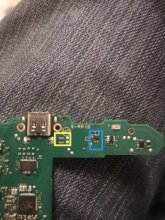
I just noticed something when I was going to take the esd chip off.

I was measuring the device I have marked In Blue, I totally missed that there is an unpopulated area closer to the usb connector ( marked in yellow) and looking at the traces I am thinking it is this unpopulated space that you were referring to.

I have measured 1-5, 2-4 and 2-5 at this unpopulated area and they are all clear. I also measure good continuity from the pins in the usb connector to the test points next to the unpopulated area.

Edit: I have done a bit more poking this morning. These two lines make it all the way from the usb-c connector (using a breakout plug) up to pins 35 and 36 on the m92t36.
 

Attachments

  • IMG_20210323_001338.jpg
    IMG_20210323_001338.jpg
    1.5 MB · Views: 167
Last edited by OwenG123,

Pintglass

Well-Known Member
Member
Joined
Jan 28, 2019
Messages
364
Trophies
0
Age
52
XP
782
Country
United Kingdom
I just noticed something when I was going to take the esd chip off.

I was measuring the device I have marked In Blue, I totally missed that there is an unpopulated area closer to the usb connector ( marked in yellow) and looking at the traces I am thinking it is this unpopulated space that you were referring to.

I have measured 1-5, 2-4 and 2-5 at this unpopulated area and they are all clear. I also measure good continuity from the pins in the usb connector to the test points next to the unpopulated area.

Edit: I have done a bit more poking this morning. These two lines make it all the way from the usb-c connector (using a breakout plug) up to pins 35 and 36 on the m92t36.

Yeah that’s where CC1 and CC2 end up at the M92T36 so if I where you I would just change that IC or you could test to see if these lines respond to the cable being inserted but it’s a bit of a faff
 

OwenG123

Member
OP
Newcomer
Joined
Mar 21, 2021
Messages
15
Trophies
0
Age
39
XP
67
Country
United Kingdom
Thanks for your help, I have some replacement M92T36 on order, when they arrive I will swap it out and see if that solves the issue.
 

Site & Scene News

Popular threads in this forum

General chit-chat
Help Users
  • No one is chatting at the moment.
    Veho @ Veho: Nobody is reading what you post.