OLED problem - Persistent error *== (help)

LucasRomeiro

Member
OP
Newcomer
Joined
Sep 30, 2023
Messages
16
Trophies
0
Age
36
XP
148
Country
Brazil
Hello, I received 3 consoles (OLED switch) from different customers and all 3 have the same problem.

All 3 are unlocked but arrived with problems!

Two of them used HWFLY and it stopped working.

The third one used PICOFLY but it stopped working too.

They were all opened and I checked all the soldering points and everything seems to be ok.

I found that one of them was an unlocking attempt that went wrong, the customer tried to do it at home and removed the resistor from point A.

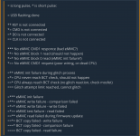
But I soldered a similar resistor to the point and it didn't work, could it be that having soldered a PTH resistor was the problem? I tried several ways and it didn't work. I always get the yellow blinking error *== (indicates error in CMD1).

The other consoles have the same *== error but still have their original resistors.

I've spent many hours on these 3 devices and haven't found any solution.


Has anyone been through this and can help me?


I did some research and didn't find anyone...
 

HawaiianInTown

Friendly Neighborhood Hawaiian
Member
Joined
Dec 1, 2023
Messages
215
Trophies
0
XP
365
Country
United States
Are you the installer, please share pictures of soldering and diode mode readouts for all probed points all all consoles. Just because it looks good, doesn't mean it is. Use screens screenshots for example...

EDT: If you are installer, I suggest you save screenshots for future reference to stress test your installs before sending consoles out. If you're not installer is still a good reference moving forward.
 

Attachments

  • Screenshot_20231208-120047.png
    Screenshot_20231208-120047.png
    535.9 KB · Views: 19
  • Screenshot_20231208-072019_1.png
    Screenshot_20231208-072019_1.png
    251.6 KB · Views: 15
  • Like
Reactions: Lamcza

LucasRomeiro

Member
OP
Newcomer
Joined
Sep 30, 2023
Messages
16
Trophies
0
Age
36
XP
148
Country
Brazil
Are you the installer, please share pictures of soldering and diode mode readouts for all probed points all all consoles. Just because it looks good, doesn't mean it is. Use screens screenshots for example...

EDT: If you are installer, I suggest you save screenshots for future reference to stress test your installs before sending consoles out. If you're not installer is still a good reference moving forward.
Thanks!


I checked all the points several times and I've been doing this for a long time, I've been doing unlocking for a long time and I know the welds are good. But I don't understand why this happens in some cases, they are very rare cases, I notice that it happens more when the console was moved by the customer and the resistor at point A came loose.

The images:
1704244036869.png


A point:
Diode read: 348
1704244101397.png


Postfix point:
Diode read: 572

1704244208008.png


B point:
Diode read: 331

1704244345808.png

Post automatically merged:

Show us pic of your soldering.
Same problem then:

1 faulty, shit happens
2 faulty, bad luck
3 faulty, you are doing something wrong/bad
see the images. maybe you can find one error
 
  • Like
Reactions: HawaiianInTown

linuxares

The inadequate, autocratic beast!
Global Moderator
Joined
Aug 5, 2007
Messages
13,324
Trophies
2
XP
18,186
Country
Sweden
Are the SP1 and SP2 really be DROWNED like that? Aren't you not just suppose to hook them up on each side without bridging the gap?
 

rull_bull

Well-Known Member
Newcomer
Joined
Nov 4, 2023
Messages
94
Trophies
0
Age
39
XP
260
Country
Sweden
Are the SP1 and SP2 really be DROWNED like that? Aren't you not just suppose to hook them up on each side without bridging the gap?

No the caps that you are soldering to dont have the same direction as the caps in the middle.
So everything there is fine.

There is nothing that sticks out after looking at your pictures.
Some points dont look so shiny. high temp, lack of flux?
And the cooling paste is a mess.

I only looked at the soldering part, regarding wire routing etc. maybe someone else could give you some feedback that have done many oleds.
 

LucasRomeiro

Member
OP
Newcomer
Joined
Sep 30, 2023
Messages
16
Trophies
0
Age
36
XP
148
Country
Brazil
No the caps that you are soldering to dont have the same direction as the caps in the middle.
So everything there is fine.

There is nothing that sticks out after looking at your pictures.
Some points dont look so shiny. high temp, lack of flux?
And the cooling paste is a mess.

I only looked at the soldering part, regarding wire routing etc. maybe someone else could give you some feedback that have done many oleds.


Thank you for your help. Everything seems right. I used the flux properly and welded it well. It's just that the microscope image doesn't look good in the photo.

I can't understand why these errors occur specifically at this point A.
 

Site & Scene News

Popular threads in this forum

General chit-chat
Help Users
  • No one is chatting at the moment.
    Metoroid0 @ Metoroid0: im more interested in metroid prime 4