Hacking Hardware McFly - an RP2040 board compatible with Picofly

KingMo5h

Active Member
Newcomer
Joined
Mar 12, 2023
Messages
26
Trophies
0
Age
33
XP
139
Country
Germany
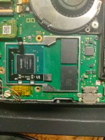
I tried my best on the space between cpu and ram. Not much space there. I guess it should work but cant link it here, since not enough post written...
Post automatically merged:

https://abload.de/img/slim0teob.jpg

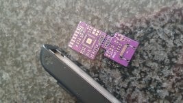
Maybe it works now. The left part is the actuell part you put in between, the right one ist just for flashing and should be removed after.
 

KingMo5h

Active Member
Newcomer
Joined
Mar 12, 2023
Messages
26
Trophies
0
Age
33
XP
139
Country
Germany
Also the top right part is are the mosfets but since i dont know the space or have the measurements. I cant design it.
It is for a 2 Layer PCB with a maximum thickness of 0.6mm, then it should fit under the shield.
 

LogicalMadness

Well-Known Member
Member
Joined
Nov 3, 2014
Messages
287
Trophies
0
Age
41
XP
690
Country
United States
Cut the bar that runs across?
 

Attachments

  • IMG20230326134925.jpg
    IMG20230326134925.jpg
    4.4 MB · Views: 72

Saliciae

Well-Known Member
OP
Newcomer
Joined
Mar 20, 2023
Messages
83
Trophies
0
Age
24
XP
419
Country
United Kingdom
U can still put a thin layer of soldermask on the bottum if it need to
but the RP2040 chip goes on top, soldermask applied by hand will stop the chip soldering properly. Best solution is not have vias under chip, but second best solution is order with tented vias
 
  • Like
Reactions: impeeza

musashiro

Member
Newcomer
Joined
Jan 12, 2020
Messages
17
Trophies
0
Age
39
XP
113
Country
Australia
do we still need to solder anything? either way, I am still happy to hear any developments for the switch, keep up the good work folks
 

Saliciae

Well-Known Member
OP
Newcomer
Joined
Mar 20, 2023
Messages
83
Trophies
0
Age
24
XP
419
Country
United Kingdom
Components are on their way too. Hopefully this weekend i can get some put together and measure the thickness, I think the whole board with components will by 1.6mm with the flat flex connector, possible thinner without it, so no case bending to make it fit!

I'm also exploring porting an RCM injector firmware like switchME or Fusee Suite to the rp2040 giving this board usage in unpatched switches (like mine :P) but it should be a useful development board for lots of space constrained applications i think
 

Gardosen

Member
Newcomer
Joined
Dec 14, 2017
Messages
6
Trophies
0
Age
37
XP
63
Country
Germany
@Saliciae any plans to release a components list + schematic where to put which piece?
I think this would be pretty nice, as i for myself would love to build the mcfly (Amazing name btw) myself for me and a friend.
 
  • Like
Reactions: impeeza

gokuz

Well-Known Member
Member
Joined
Jun 13, 2014
Messages
145
Trophies
0
XP
638
Country
Senegal
Mosfets should be as close to the APU as possible for best results.
Time to debunk this once and for all. The original flex cable has quite a distance from the capacitors. Its more of a design choice that has been used since SX. No reason the mosfet incorporated in the main chip will work differently.

The only reason the "close to the APU" is a thing is because of the beta people trying out stuff to make their lives easier by soldering it directly to the capacitor.
 

Site & Scene News

Popular threads in this forum

General chit-chat
Help Users
  • No one is chatting at the moment.
    SylverReZ @ SylverReZ: People are gonna find loopholes around clan tags and make inappropriate names.