


I want to put a USB-C port on my DSi, so I wanna know if there´s a circuit diagram or pcb file of the DSi so I can find a proper way to get the 5V of the USB down to the 4.6V of the DSi.
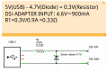
I thought of something like this:

Using a 4.7V Zener diode (should be close enough to 4.6V) to limit the voltage and a resistor to limit the current.
A circuit diagram would really help me out, since I dont knpw how the DSi handles power internally.
Update: Apparently my powerbank outputs 5.3V and the DSi can handle it without problems. So i just replaced the old Port with USB-C and it works.
About the old charger, it´s dead, 3.5V without load.
I thought of something like this:
Using a 4.7V Zener diode (should be close enough to 4.6V) to limit the voltage and a resistor to limit the current.
A circuit diagram would really help me out, since I dont knpw how the DSi handles power internally.
Update: Apparently my powerbank outputs 5.3V and the DSi can handle it without problems. So i just replaced the old Port with USB-C and it works.
About the old charger, it´s dead, 3.5V without load.
Attachments
Last edited by Nercer,


