Hello,
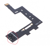
I've installed an HwFly RP2040 chip on my Mariko switch. I did everything as I should have done it, and when I turn on the Switch, the LED blinks blue, then yellow a bunch of times and the Switch boots into OFW. What does that mean? Here are some pics:

I used a multimeter to measure the resistance of both sides of the SP2 contact points and it reads 11.2 ohms.

Between the points of the pads of SP1 it reads 9.9 ohms.
Is this a poor soldering job, defective chip, or it needs flashing?
I've installed an HwFly RP2040 chip on my Mariko switch. I did everything as I should have done it, and when I turn on the Switch, the LED blinks blue, then yellow a bunch of times and the Switch boots into OFW. What does that mean? Here are some pics:
I used a multimeter to measure the resistance of both sides of the SP2 contact points and it reads 11.2 ohms.
Between the points of the pads of SP1 it reads 9.9 ohms.
Is this a poor soldering job, defective chip, or it needs flashing?