5v rail short - Please help!!

lpoolm

Well-Known Member
OP
Member
Joined
Jun 20, 2017
Messages
419
Trophies
0
Age
45
XP
2,416
Country
United Kingdom
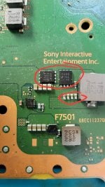
I have a short on my 5v rail. It is showing on the 4 caps shown in picture 1. I have seen these caps go bad often but my issue seems different to others!
What I have done is inject voltage 1.5v up to 2v but nothing gets warm (tried on both sides?)
I removed the 4 caps to test, tested good and still had the short on the board.
Removed the 2 mosfets above and still had the short?
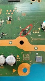
On the other side of the board the two caps circled in pic 2 show as short, I removed them and the mosfet and the short is still there?
I have checked around the board but cannot find anything else shorted? I have checked all fuses and all test good.
I am now out of ideas so any ideas would be great thanks!
20230619_182807.jpg20230619_183110.jpg
 

The Real Jdbye

*is birb*
Member
Joined
Mar 17, 2010
Messages
23,317
Trophies
4
Location
Space
XP
13,899
Country
Norway
I have a short on my 5v rail. It is showing on the 4 caps shown in picture 1. I have seen these caps go bad often but my issue seems different to others!
What I have done is inject voltage 1.5v up to 2v but nothing gets warm (tried on both sides?)
I removed the 4 caps to test, tested good and still had the short on the board.
Removed the 2 mosfets above and still had the short?
On the other side of the board the two caps circled in pic 2 show as short, I removed them and the mosfet and the short is still there?
I have checked around the board but cannot find anything else shorted? I have checked all fuses and all test good.
I am now out of ideas so any ideas would be great thanks!

View attachment 378868View attachment 378869
FWIW i would be careful injecting more than 0.5-1v. The power could get passed directly through a MOSFET or power regulator into components that are designed for less than that.
If you can't feel anything getting warm, spraying some IPA on the components and seeing where it evaporates quickest can often be a more effective method as it's more sensitive.
 

lpoolm

Well-Known Member
OP
Member
Joined
Jun 20, 2017
Messages
419
Trophies
0
Age
45
XP
2,416
Country
United Kingdom
FWIW i would be careful injecting more than 0.5-1v. The power could get passed directly through a MOSFET or power regulator into components that are designed for less than that.
If you can't feel anything getting warm, spraying some IPA on the components and seeing where it evaporates quickest can often be a more effective method as it's more sensitive.
Yer I won't go higher. I have a thermal cam and it shows nothing
 

lpoolm

Well-Known Member
OP
Member
Joined
Jun 20, 2017
Messages
419
Trophies
0
Age
45
XP
2,416
Country
United Kingdom
Damn, was going to suggest looking something overheating with a Thermocam...
Maybe... a trace is broken?
Have you checked continuity in every trace?
No, this is my first ps5 and its been a bugger! I normally just do Switchs.
Wouldn't know where to start with continuity as not sure where the traces go from one side to the other?
 

JuanMena

90's Kid, Old Skull Gamer & Artist
Member
Joined
Dec 17, 2019
Messages
4,895
Trophies
2
Age
30
Location
the 90's 💙
XP
10,139
Country
Mexico
No, this is my first ps5 and its been a bugger! I normally just do Switchs.
Wouldn't know where to start with continuity as not sure where the traces go from one side to the other?
There should be testing points, or with a bright light, depending on the thickness of the layers could be possible to see through the pcb.

Have you checked for missing transistors/resistors?
 

The Real Jdbye

*is birb*
Member
Joined
Mar 17, 2010
Messages
23,317
Trophies
4
Location
Space
XP
13,899
Country
Norway
Yer I won't go higher. I have a thermal cam and it shows nothing
I mean, 1.5-2v even seems like too much.
Surprisingly, IPA can be more effective than thermal imaging. Thermal cameras are just so low resolution that they're not very good at detecting a very slight change in heat in a concentrated spot. Just recently saw a repair video where nothing out of the ordinary showed up on thermal imaging, but it was apparent right away by spraying IPA on any suspected faulty components. The heat was concentrated near one leg of a chip, too small and weak for the thermal camera to pick up.
 

lpoolm

Well-Known Member
OP
Member
Joined
Jun 20, 2017
Messages
419
Trophies
0
Age
45
XP
2,416
Country
United Kingdom
I mean, 1.5-2v even seems like too much.
Surprisingly, IPA can be more effective than thermal imaging. Thermal cameras are just so low resolution that they're not very good at detecting a very slight change in heat in a concentrated spot. Just recently saw a repair video where nothing out of the ordinary showed up on thermal imaging, but it was apparent right away by spraying IPA on any suspected faulty components. The heat was concentrated near one leg of a chip, too small and weak for the thermal camera to pick up.
I will try it but I removed most of the parts around the shorted area so I think it might be a chip linked but somewhere else on the board?
 

Johnny_debt

Well-Known Member
Newcomer
Joined
Mar 29, 2022
Messages
57
Trophies
0
XP
438
Country
United States
Are you sure you have a short on the 5v rail? The first picture, I believe that is the 12v rail on the 4 larger capacitors circled in your picture. On my edm-010 board the 5v is generated at F7001.
 

lpoolm

Well-Known Member
OP
Member
Joined
Jun 20, 2017
Messages
419
Trophies
0
Age
45
XP
2,416
Country
United Kingdom
Are you sure you have a short on the 5v rail? The first picture, I believe that is the 12v rail on the 4 larger capacitors circled in your picture. On my edm-010 board the 5v is generated at F7001.
You might be right, I thought it was 5v? But I still have a short unfortunately.
 

Johnny_debt

Well-Known Member
Newcomer
Joined
Mar 29, 2022
Messages
57
Trophies
0
XP
438
Country
United States
You might be right, I thought it was 5v? But I still have a short unfortunately.
Check on diode mode, red probe on ground (use one of the dots on the side of the board) and black on those capacitors (non ground side). Do you have a short? The 12v can show up as short momentarily but that's normal.

I did check my edm-010 board and in your first picture, the smaller caps are indeed 5v.
 
Last edited by Johnny_debt,
  • Like
Reactions: lpoolm

jkyoho

Well-Known Member
Member
Joined
Sep 2, 2020
Messages
1,282
Trophies
0
Age
39
Location
TORONTO
Website
form.jotform.com
XP
2,210
Country
Canada
pic1 2x mosfet gens 5v from psu 12v through 1R5 inductor and those 4 caps in a row. Then this 5v goes to the pic2 IC and become 5v source for the front USB I/O panel.

check yellow arrow cap if any short and remove picture2 black ic and see if your 5v short gone.

1687361854243.png
 

Johnny_debt

Well-Known Member
Newcomer
Joined
Mar 29, 2022
Messages
57
Trophies
0
XP
438
Country
United States
pic1 2x mosfet gens 5v from psu 12v through 1R5 inductor and those 4 caps in a row. Then this 5v goes to the pic2 IC and become 5v source for the front USB I/O panel.

check yellow arrow cap if any short and remove picture2 black ic and see if your 5v short gone.

View attachment 379159
I actually have the same issue on an EDM-020 or I think I have the same issue. For me the red circled areas have 12ohm resistance to ground. I removed the IC and the caps, along with the electrolytic cap to the right. On other other side of the board, I removed the inductor and isolated the 12 ohm reading to the 4 smaller caps, I removed these caps. There is an IC to the right of these caps, its a texas instrument IC, I also removed. No change to the 12 ohm reading. I know this 5v area goes to the NCP252120 integrated driver / mosfet as VCC for those ICs. I removed those also. Still zero change to the 12 ohm reading. I think I'm chasing a red herring, maybe 12 ohms on a board that hasn't been powered on for half a year is correct?

This board has no signs of life, thought this of been the issue.

edit: definitely not a red herring. The 12 ohm reading is odd, I don't know where it goes, seems to be a trace that goes into layers in board but don't know exactly where. I removed all the mosfets that power the apu (vcc is connected to 5v here), removed all the components off the 5v line and expected to get OL on my meter but still the same 12 ohm reading. The 12 ohm reading is causing excess current in the APU mosfets, so if attempting to power the ps5 the APU mosfet blows and causes a 12v short, psu cuts off into protection mode. This was how it was when I started working on this since I thought it was a 12v at apu mosfets which I changed to resolve. It seems the 5v 12 ohm reading is causing the apu mosfets to blow and short 12v. So without resolving the 5v 12 ohm reading, any remedy on 12v short won't work. I checked on working edm-020 disc board and the 5v rail should read approx 6k ohm resistance to ground.

Anyone have any idea where this line eventually ends up?
 
Last edited by Johnny_debt,
  • Like
Reactions: lpoolm

Site & Scene News

Popular threads in this forum

General chit-chat
Help Users
    K3Nv2 @ K3Nv2: Meta what's @Psionic Roshambo onlyfans password