Buddy, you got it, your adapter, charger, power supply, brick, etc. (what ever you called it) is a semi intelligent device. isn't like the older USB chargers which only are power supply of 5 volts and whatever current allowed/asked by the device.
the new type of chargers use a protocol called PD (Power Delivery)
https://www.goalzero.com/blogs/news/what-the-tech-usb-c-and-power-delivery-explained that protocol allows to the device and charger "talk" and agree the Power of the electricity deliver, power refers not only to Voltage also Amperage. That's why the charger is rated as 5V/1.5A (7 Watts) & 15V/2.5A (37.5 Watts).
When charged is disconnected the charger have no voltage between his +V - GND wires.
Then when connected to a device the communication wire is used to negotiate a power to delivery on terms of Voltage and Current.
most of the USB-C connectors are semi-breakthrough boards, that's mean what you dont have directly access to each pin of the connector but the circuit board have some tracks and connect some pins with other and have pads for you to solder wires.
USB-C Pinout:
View attachment 330327
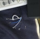
if you look the original pictures you provide, you can identify 4 solder pads, I marked with brown, light brown, blue and red lines
View attachment 330323
The red lines are connected to pins A4, A9, B4 & B9 which on the Pinout for USB-C connector correspond to VBUS (as marked on the pcb)
The Brown lines are connected to pins A12 & B1 and the light Brown ones to A1 & B12 all of then correspond to GND on USB-C pinout
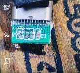
And the Blue lines are connected to A5 (CC1).
The pic CC1 is the responsible to indicate to the power source what type of connection the device wants.
Also you must note what the pins A6 & A7 (D+ & D-) are shorted AT CONNECTOR, so the device knows what the cable connected to his port is from a power bank and no a device for data transmission. Theoretically the B6 & B7 pins should be shorted too, but that could be managed internally by the board with multi layer pcb or on the device as asked by the USB RFC
Most of the commercial USB-Connectors are like:
View attachment 330331View attachment 330332
as you can see you have access to some pins, but no to the CC1 pin which is managed by the board with the resistors included.
This connectors are used for "data cables" or OTG whn you move the included resistor to the free pads, a typical OTG connection is:
View attachment 330339
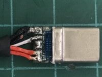
So you need a connector with access to all pins and make the internal connections between A6&A7, and connect the CC1 cable to the correspondent pin.
There are two VBUS and GND cables for the amperage management, you better use two "thin" cables than a very thick cable to deliver the same current.
hope be clear enough to give you an advance.