Ok please help.
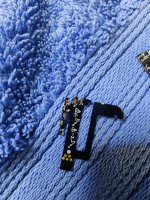
first thing i have recieved info to cut part of this chip do i have to do it?

2nd question we having hard time to solder A and C and D points due to lack of copper any tips please?
im getting my friend help as well who is experienced with soldering but still we cant solder it!
we used flex and chisel tip solder what tip have you guys used and would recommened ? any tips? thanks heaps pleaasee.

first thing i have recieved info to cut part of this chip do i have to do it?
2nd question we having hard time to solder A and C and D points due to lack of copper any tips please?
im getting my friend help as well who is experienced with soldering but still we cant solder it!
we used flex and chisel tip solder what tip have you guys used and would recommened ? any tips? thanks heaps pleaasee.