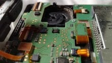
Hey, yes the trances are ripped off.
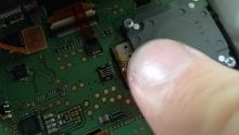
Furthermore, I think i've damaged the pins beyond repair, trying to move them back into position, see the attached image.
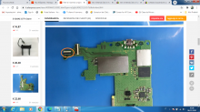
I appreciate the help guys but this seems to have been beyond my capabilities. I do have a new circle stick mechanism with new ribbons coming in the post but It doesn't look like I'll be able to repair the pins.
If anyone would like the system, as I won't be able to use it now, I can post it anywhere in the UK.
Furthermore, I think i've damaged the pins beyond repair, trying to move them back into position, see the attached image.
I appreciate the help guys but this seems to have been beyond my capabilities. I do have a new circle stick mechanism with new ribbons coming in the post but It doesn't look like I'll be able to repair the pins.
If anyone would like the system, as I won't be able to use it now, I can post it anywhere in the UK.